Array substrate, display panel and electronic equipment

An array substrate and color filter substrate technology, applied in the field of display equipment, can solve the problems of uneven display and different loads, and achieve the effect of reducing the load difference and improving the display quality.

Active Publication Date: 2021-10-29
HKC CORP LTD
View PDF7 Cites 1 Cited by
  • Summary
  • Abstract
  • Description
  • Claims
  • Application Information

AI Technical Summary

Problems solved by technology

[0004] The main purpose of this application is to propose an array substrate. By designing the metal wiring at the imaging hole and the cutout of the array substrate, the metal wiring at the imaging hole and the rest of the metal wiring have the same load value, thereby Solve the problem of uneven display caused by different loads

Method used


Image

  • Array substrate, display panel and electronic equipment
  • Array substrate, display panel and electronic equipment
  • Array substrate, display panel and electronic equipment

Examples


Embodiment 1

[0046] The present application provides an array substrate 100 .

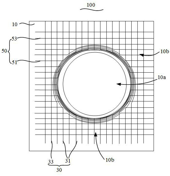
[0047] Please refer to Figure 1 to Figure 4 , the array substrate 100 includes a substrate 10 and a plurality of parallel scanning lines 50 and a plurality of parallel data lines 30 arranged on the substrate 10, each of the scanning lines 50 is perpendicular to each of the data lines 30 Arranged in a staggered manner, the substrate 10 is provided with an imaging hole area 10a;

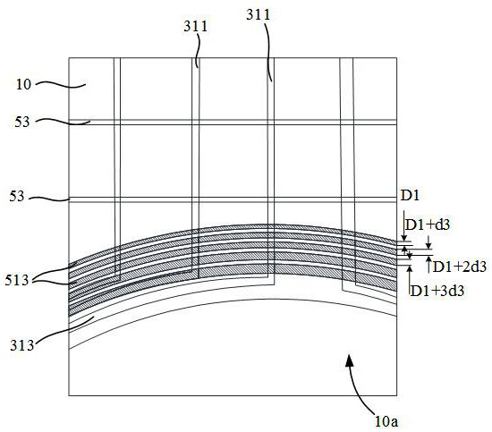
[0048] At least two parts of the data line 30 are arranged around the imaging aperture area 10a, at least two parts of the scanning line 50 are arranged around the imaging aperture area 10a, and the setting part is arranged around the imaging aperture area 10a. The scanning line 50 of the imaging aperture area 10a is the first scanning line 51, the scanning line 50 not surrounding the imaging aperture area 10a is the second scanning line 53, and the data line 30 surrounding the imaging aperture area 10a is set as The first data line ...

Embodiment 2

[0069] Please refer to Figure 5 and Figure 6 , when the shape of the imaging hole area 10a is a drop shape;

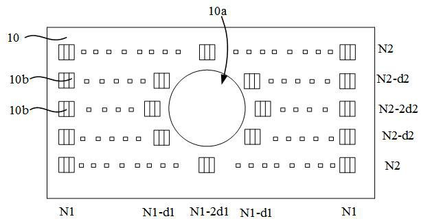
[0070] In the extending direction of the data line 30 from one end away from the imaging aperture area 10a to the imaging aperture area 10a, the number of pixel units 10b formed by two adjacent first scanning lines 51 and data lines 30 is equal to or greater than Decrease in the first unequal progression;

[0071] Moreover, in the direction from the second scanning line 53 to the center of the imaging aperture area 10a, the number of pixel units 10b formed by two adjacent first data lines 31 and scanning lines 50 is the second unequal difference. Decremented sequence.

[0072] In this embodiment, the imaging aperture area 10a is in the shape of a water droplet, which is an inverted shape of a normally falling water droplet, that is, in the vertical direction, the upper dimension of the imaging aperture area 10a is larger and the lower dimension is smaller. Theref...

Embodiment 3

[0081] Please refer to Figure 9 and Figure 10 , when the imaging aperture area 10a is bangs-shaped, in the extending direction of the data line 30 from the end far away from the imaging aperture area 10a to the imaging aperture area 10a, two adjacent first scanning lines The number of pixel units 10b formed by 51 and the data line 30 is decreased by the first non-arithmetic sequence;

[0082] Moreover, in the direction from the second scanning line 53 to the center of the imaging aperture area 10a, the number of pixel units 10b formed by two adjacent first data lines 31 and scanning lines 50 is the second unequal difference. Decremented sequence.

[0083] In this embodiment, when the imaging hole area 10a is notch-shaped, the notch-shaped shape is roughly trapezoidal, with a slightly wider upper end and a slightly narrower lower end. 30 is neither axisymmetrically arranged nor centrosymmetrically arranged. In the horizontal direction, the scanning lines 50 and the data l...


PUM


Abstract

The invention discloses an array substrate, a display panel and electronic equipment. The array substrate comprises a substrate body, scanning lines and data lines, the scanning lines and the data lines are perpendicularly arranged in a staggered mode, the substrate body is provided with a camera hole area, the scanning line partially surrounding the camera hole area is set as a first scanning line, and the scanning line not surrounding the camera hole area is set as a second scanning line. The data line surrounding the camera hole area is set as a first data line, and the scanning line not surrounding the camera hole area is set as a second data line; and in the direction from the edge of the camera hole area to the center of the camera hole area, the width of the part, surrounding the camera hole area, of the first data line and/or the first scanning line is gradually increased. According to the array substrate in the technical scheme, by widening the sections of the scanning lines and the data lines in the camera hole area, the increased wiring length and the reduced pixel number due to the fact that the camera hole area occupies are compensated, then it is guaranteed that the resistance loads and the capacitance loads of all the positions are the same, and the problem of uneven display is solved.

Description

technical field [0001] The present application relates to the technical field of display devices, in particular to an array substrate, a display panel and electronic devices. Background technique [0002] Today, mobile electronic devices have become an indispensable part of people's daily life, such as smart phones, tablet computers, and the like. Generally speaking, these electronic devices all have a camera function, including front and rear cameras. And with the popularity of ultra-narrow bezel design, some products put the front camera inside the display screen, that is, the design of the hole-punch screen or the water drop screen. For mobile electronic devices using liquid crystal displays (LCDs), in order to To ensure that the camera function is not affected, there must be no metal wiring around the glass camera hole (Camera hole) on the array substrate side of the LCD, that is, the metal wiring needs to avoid the camera hole. [0003] At present, in mobile electroni...

Claims


Application Information

Patent Timeline
Patent Type & Authority Applications(China)
IPC IPC(8): G02F1/1362
CPCG02F1/1362G02F1/136286
Inventor 毛晗郑浩旋
Owner HKC CORP LTD
Why Eureka
Try Eureka