
Linkage type auxiliary clamping and fixing device for pipeline laying
A fixing device and auxiliary clamping technology, which is applied in the field of auxiliary clamping and fixing devices for linked pipeline laying, can solve the problems of time-consuming and laborious, inconvenient channel steel or continuous lifting of pipelines, etc., and achieve the effect of convenient and quick installation.
- Summary
- Abstract
- Description
- Claims
- Application Information
AI Technical Summary
Problems solved by technology
Method used
Image

Examples
Embodiment Construction
[0026] Based on the embodiments of the present invention, all other embodiments obtained by persons of ordinary skill in the art without making creative efforts belong to the protection scope of the present invention.
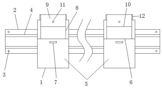
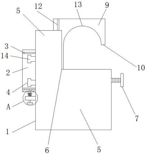
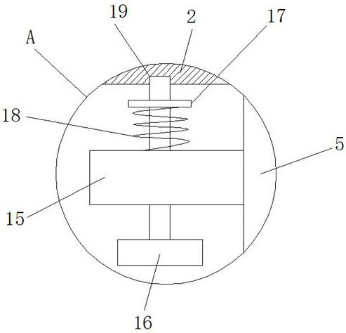
[0027] see Figure 1-7 , the present invention provides a technical solution: an auxiliary clamping and fixing device for interlocking pipeline laying, including a fixing device body 1, a mounting seat 2, a mounting hole 3, a guide groove 4, a lower fixing structure 5, a placing table 6, a tightening Fixing screw 7, installation opening 8, upper fixing structure 9, placement opening 10, fastening hole 11, limit bar 12, upper clamping opening 13, guide block 14, support frame 15, pulling head 16, pulling plate 17, spring 18. Limiting hole 19, pushing plate 20, receiving groove 21, sliding groove 22, lower clamping opening 23, mounting groove 24, supporting plate 25 and limiting platform 26, the fixing device body 1 is provided with a mounting seat 2, And the mo...
PUM
 Abstract
Description
Claims
Application Information