Aerial imaging device

An aerial imaging and real image technology, applied in the field of optical imaging, can solve the problems of inability to apply to small and portable electronic devices, and the size of the equipment is large, and achieve the effect of reducing the viewing angle and volume

Pending Publication Date: 2021-11-12
ANHUI EASPEED TECHNOLOGY CO LTD
View PDF5 Cites 1 Cited by
  • Summary
  • Abstract
  • Description
  • Claims
  • Application Information

AI Technical Summary

Problems solved by technology

[0003] Due to the dependence of the imaging quality on the angle between the imaging element and the display element, the non-contact aerial imaging equipment currently on the market results in too large equipment volume, which cannot meet the compactness requirements of today's electronic devices, and cannot be applied to small and portable devices. electronics

Method used


Image

  • Aerial imaging device
  • Aerial imaging device
  • Aerial imaging device

Examples


Embodiment Construction

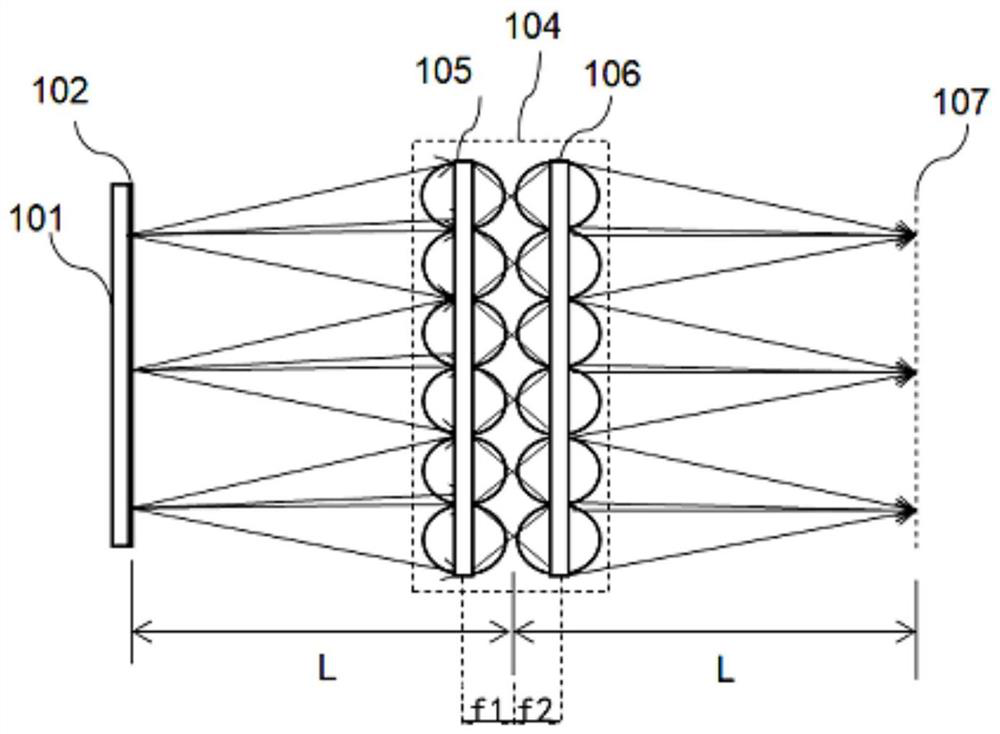
[0035] Embodiments of the present invention are described in detail below, and the embodiments described with reference to the accompanying drawings are exemplary, and reference is made below Figure 1-Figure 11 An aerial imaging device 100 according to an embodiment of the present invention is described.

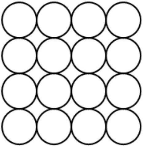
[0036] Such as figure 1 As shown, the aerial imaging device 100 according to the embodiment of the first aspect of the present invention includes: a display element 101 , a first microlens array 105 , and a second microlens array 106 .

[0037] The display element 101 has a plurality of pixels for displaying images. The display part 101 may be a plane or a curved surface, and may be a collection of one or a plurality of planar display parts 101, and each planar display part 101 may be in a different spatial position. The viewing angle of the display member 101 is relatively small, and the viewing angle perpendicular to the display plane and deviated from the normal can ra...


PUM


Abstract

The invention discloses an aerial imaging device. The aerial imaging device comprises a display part, a first microlens array and a second microlens array, wherein the display part is provided with a plurality of pixel points; the first microlens array is located on one side of the display part and faces the multiple pixel points, the distance between the display part and the first microlens array is L, the focal length of the first microlens array is f1, and L is larger than or equal to 2f1; the second microlens array is located on the side, away from the display part, of the first microlens array, and the focal length of the second microlens array is f2; the two microlens arrays are respectively provided with a plurality of sub-lenses, the sub-lenses are in one-to-one correspondence in the optical axis direction, light emitted by each pixel point enters at least one sub-lens, and an image of the display part passes through the first microlens array and the second microlens array and then forms a floating real image on the side, away from the first microlens array, of the second microlens array. Therefore, the imaging device is small in size, the generated real image is free of overturning and mirror images, and observation can be carried out at any distance within the visual angle range.

Description

technical field [0001] The invention relates to the technical field of optical imaging, in particular to an aerial imaging device. Background technique [0002] The microlens array is an array composed of lenses with a clear aperture of micrometers and a relief depth of nanometers. The array unit is small in size and highly integrated, and has functions such as focusing and imaging. At present, it is mainly used in wavefront sensing, infrared focal plane detection, CCD array light concentration, laser array scanning, laser display, fiber coupling and other systems. At present, the non-contact aerial imaging technology on the market seldom uses microlens arrays for imaging, but mostly uses dihedral reflective arrays (DCRA). However, this technology has an obvious disadvantage. DCRA needs to be used with The object plane forms a certain angle (generally 45 degrees is the best), and it cannot be used parallel to the object plane, which leads to a larger volume of the device, a...

Claims


Application Information

Patent Timeline
Patent Type & Authority Applications(China)
IPC IPC(8): G02B30/27G02B30/56
CPCG02B30/27G02B30/56
Inventor 张亮亮李军昌
Owner ANHUI EASPEED TECHNOLOGY CO LTD
Why Eureka
Try Eureka