Reflective display device

一种反射型显示、器件的技术,应用在显示装置、仪器、光学元件等方向,能够解决回射器回射特性恶化、制造步骤复杂、不能提高白色显示模式质量等问题,达到显示模式质量及对比度提高的效果

Inactive Publication Date: 2007-08-01
SHARP KK
View PDF6 Cites 1 Cited by
  • Summary
  • Abstract
  • Description
  • Claims
  • Application Information

AI Technical Summary

Problems solved by technology

[0021] However, when the structure of Japanese Laid-Open Patent Publication No. 2002-107519 is employed, it is necessary to provide a light-absorbing surface portion for each very small-sized unit element, thereby making the manufacturing steps too complicated
To make matters worse, the retroreflective properties of the retroreflector deteriorate slightly, which does not improve the quality of the white display mode
[0022] For this reason, the structure can only increase the contrast to a limited extent

Method used


Image

  • Reflective display device
  • Reflective display device
  • Reflective display device

Examples


Embodiment approach 1

[0099]Next, a reflective display device according to a first specific preferred embodiment of the present invention will be described.

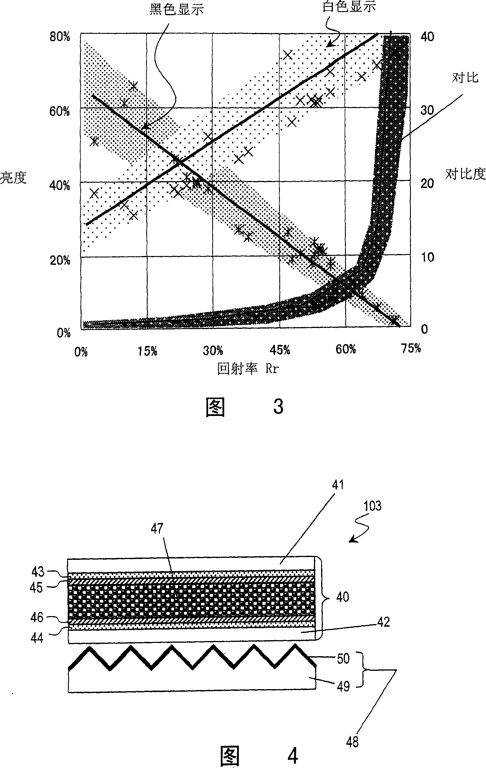
[0100] First, the structure of the display device 103 according to the preferred embodiment of the present invention will be described with reference to FIG. 4 . The display device 103 includes a retroreflector 48 and a liquid crystal cell 40 , wherein the liquid crystal cell is disposed closer to the viewer than the retroreflector 48 .

[0101] The liquid crystal cell 40 includes a pair of transparent substrates 41 and 42 facing each other and a liquid crystal layer 47 interposed between the substrates 41 and 42 . The transparent substrates 41 and 42 are made of a transparent material such as glass or a polymer film. On the surface of the transparent substrate 41 disposed close to the observer, a transparent electrode 43 and an alignment film 45 are stacked in this order so as to face the liquid crystal layer 47 . On the surface of the oth...

Embodiment approach 2

[0151] Next, a reflective display device according to a second specific preferred embodiment of the present invention will be described.

[0152] First, the structure of a display device 104 according to this preferred embodiment will be described with reference to FIG. 10 . The display device 104 of the preferred embodiment is preferably a color display device.

[0153] The display device 104 has the same structure as the display device 103 of the first preferred embodiment described above, except that the display device 104 further includes a color filter layer 51 between the transparent substrate 41 close to the observer and the transparent electrode 43 outside. More specifically, the color filter layer 51 preferably includes red (R), green (G), and blue (B) color filters, which are arranged in a regular pattern and provided between adjacent color filters. There is an opaque layer (or black matrix (BM)). Each color filter has dimensions of, for example, 50 μm×50 μm. It ...

Embodiment approach 3

[0160] Next, a reflective display device according to a third specific preferred embodiment of the present invention will be described.

[0161] First, the structure of a display device 105 according to this preferred embodiment will be described with reference to FIGS. 11 and 12 . The display device 105 of the preferred embodiment is an active matrix addressed display device.

[0162] As shown in FIG. 12 , the display device 105 preferably includes a display portion 91 and a driver circuit for driving the display portion 91 .

[0163] FIG. 11 shows a detailed structure of the display section 91. As shown in FIG. As shown in FIG. 11, the display portion 91 includes a liquid crystal layer 73 and a retroreflector 48, which are arranged between a pair of substrates 71 and 72 facing each other. The substrate 71 is an active matrix substrate including a plurality of thin film transistors 76 thereon. The retroreflector 48 includes a square corner prism array 74 disposed on a subs...


PUM

PropertyMeasurementUnit
contrastaaaaaaaaaa
contrastaaaaaaaaaa

Abstract

A reflective display includes a retroreflective layer and a modulation layer, which is provided closer to a viewer than the retroreflective layer is and which is switchable between first and second states with mutually different optical characteristics. The retroreflective layer includes a two-dimensional arrangement of unit elements, which are arranged at a pitch of at most 250 mum. The retroreflective layer has a retro-reflectivity Rr of at least 45%. The retroreflectivity is defined as a ratio of the intensity of light, which has been reflected from the retroreflective layer and then received at a cone angle of 7.5 degrees by a retroreflectivity measuring system, to that of light, which has been reflected from a dielectric mirror and then received by the same retroreflectivity measuring system.

Description

technical field [0001] The present invention relates to a reflective display device including a retroreflector and a method of evaluating the retroreflector. Background technique [0002] Various structures have been proposed for reflective liquid crystal display devices with retroreflectors (see, for example, Japanese Unexamined Patent Publication No. 2002-107519, Japanese Patent No. 3216584, and Publication No. 2002-287134 Japanese patent pending). Each of these reflective liquid crystal display devices does not use a polarizer, and thus can perform a display operation with increased brightness, and a display with higher contrast is also desired. As used herein, "retroreflector" refers to an optical element having a two-dimensional arrangement of extremely small unit elements so as to reflect any incident light back to the light source through its multiple reflective surfaces, regardless of Where is the light coming from. [0003] FIG. 19 shows a typical structure of a ...

Claims


Application Information

Patent Timeline
Patent Type & Authority Patents(China)
IPC IPC(8): G02F1/1335G02F1/1333G02B5/124G09F9/00G09F13/16
CPCG02F1/133553G02B5/124G02F1/1335
Inventor 藤原小百合箕浦洁
Owner SHARP KK
Why Eureka
Try Eureka