Polarizing element, optical element, and liquid crystal display

a technology of optical elements and liquid crystal displays, applied in static indicating devices, instruments, non-linear optics, etc., can solve the problems of reduced contrast, reduced level, reduced contrast, etc., and achieve the effect of preventing the reduction of contrast in a black display and in a reflective display mod

Inactive Publication Date: 2003-12-09
NITTO DENKO CORP
View PDF3 Cites 179 Cited by
  • Summary
  • Abstract
  • Description
  • Claims
  • Application Information

AI Technical Summary

Benefits of technology

According to the present invention, the function as a semitransparent reflective polarizer is accomplished utilizing the reflective polarizing plate. In a transmissive display mode, the polarization ratio through the absorptive polarizer is maintained, and a high contrast display can be achieved due to the high polarization ratio. Also, high luminance display can be achieved by the high utilization of a lighting light due to a high light transmittance. In a reflective display mode, the optical element absorbs and cuts off efficiently unnecessary reflected light (returned light), which is an external light reflected by a lighting device etc., so that reduced contrast in a black display etc. is prevented, and good display quality with high contrast is provided.

Problems solved by technology

This decreases the level of a black display, resulting in reduced contrast.
Thus, in the above-mentioned light-absorbing layer system, it has been difficult to prevent reduced contrast in a black display etc. in a reflective display mode.
In this case, unnecessary reflected light of an external light, which is reflected by the surface of the liquid crystal cell, etc. to interfere with the visibility of display light, is absorbed and cut off.

Method used


Image

  • Polarizing element, optical element, and liquid crystal display
  • Polarizing element, optical element, and liquid crystal display
  • Polarizing element, optical element, and liquid crystal display

Examples


example 2

A circularly polarizing plate comprising a broadband quarter wavelength plate (manufactured by Nitto Denko Corporation, a laminate of NRF of 270 nm and 140 nm; the same broadband quarter wavelength plate being used in the following examples) and an absorptive polarizing plate (the same circularly polarizing plate being used in the following examples) was adhered onto one side of a circularly polarized light separation plate, which comprises a cholesteric liquid crystal, through an acrylic adhesive layer so that the rotating direction of the circularly polarizing plate was the same as the rotating direction of a circularly polarized light transmitted through the circularly polarized light separation plate. Thus, a polarizing element was obtained.

The polarizing element exhibited the function as a semitransparent reflective polarizer. It also showed a high polarizing ratio of a transmitted light depending on the absorptive polarizing plate, and high contrast display was obtained. Compa...

example 3

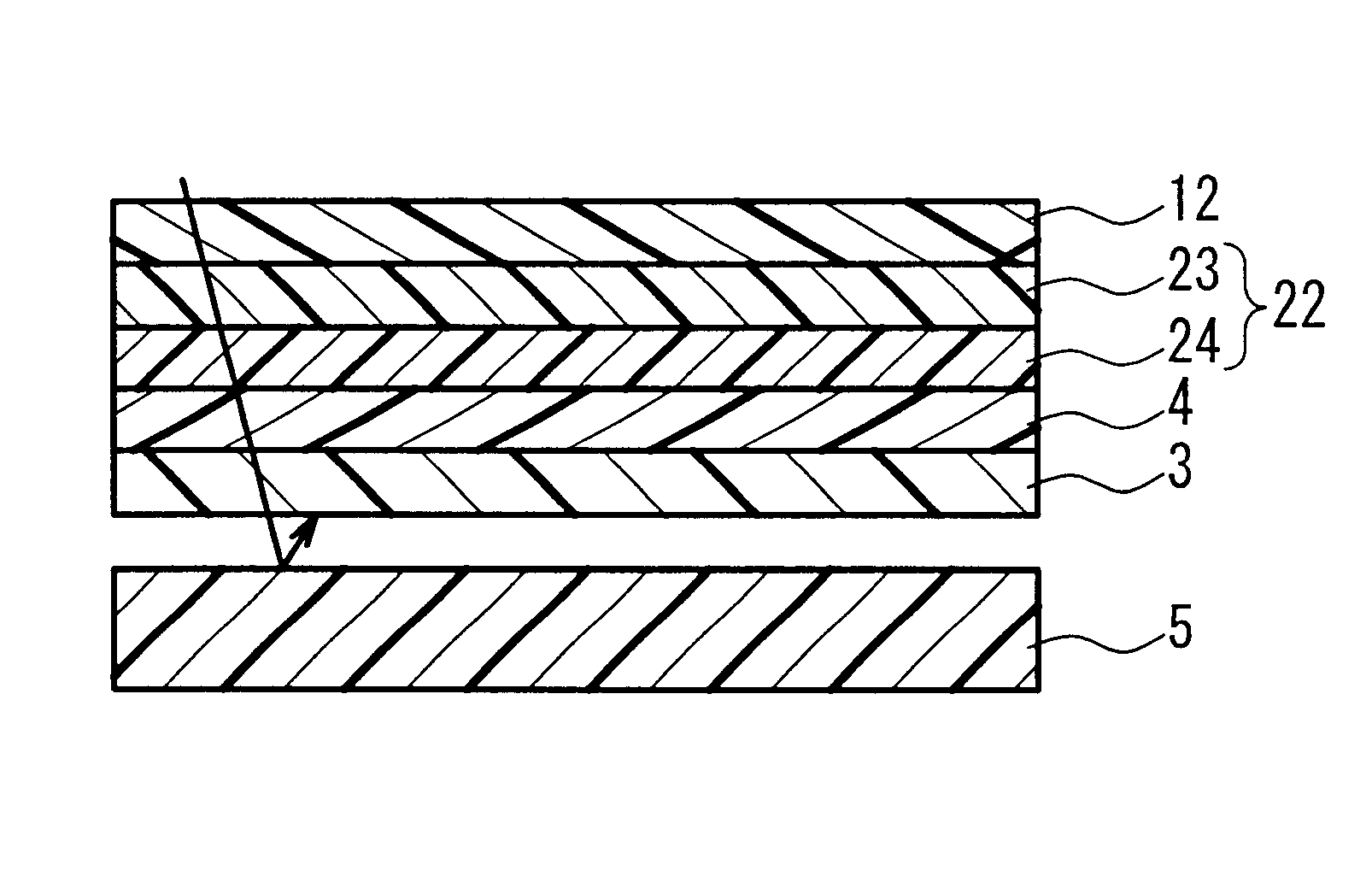
A circularly polarizing plate was adhered onto the side of the absorptive polarizing plate in the polarizing element of Example 1 through an acrylic adhesive layer so that the absorptive polarizing plates were adjacent with each other and their transmission axes were in parallel with each other. Thus, an optical element was obtained (FIG. 4). This optical element maintained the function as a semitransparent reflective polarizer. It also showed a high polarizing ratio of a transmitted light depending on the absorptive polarizing plates, and high contrast display was obtained. Compared with a simple absorptive semitransparent layer having 40% transmittance, the light utilization efficiency of a transmitted light also increased double.

With respect to the prevention of decreased contrast in a reflective display mode when a lighting device of electroluminescence system was provided on the back side, the same or greater effect was obtained than that of conventional one having a light-abso...

example 4

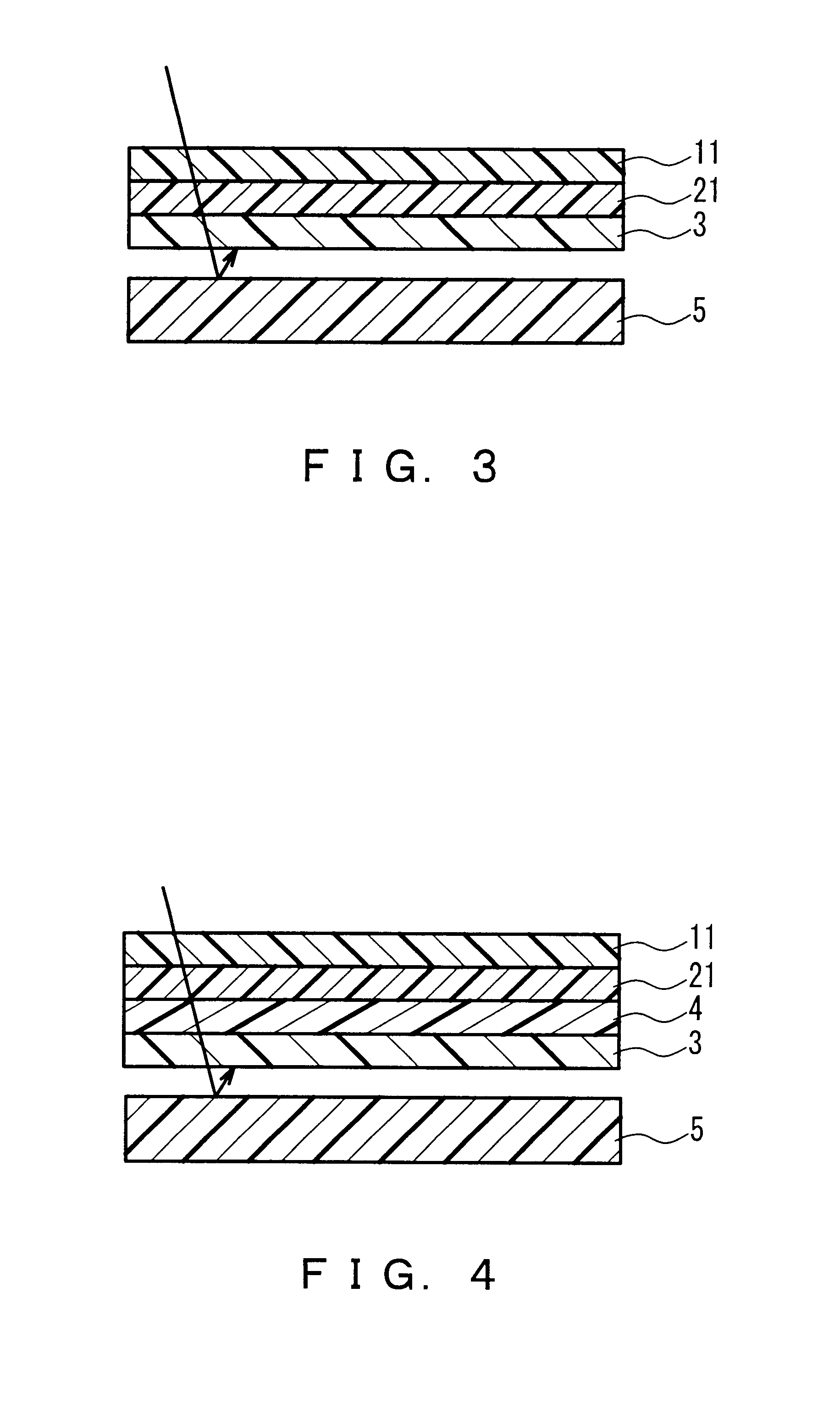
A broadband quarter wavelength plate was adhered onto the side of the absorptive polarizing plate in the polarizing element of Example 1 through an acrylic adhesive layer. Thus, an optical element was obtained (FIG. 3). This optical element maintained the function as a semitransparent reflective polarizer. This optical element exhibited excellent light transmittance and thinness. Furthermore, this optical element exhibited a high polarization ratio of a transmitted light depending on the absorptive polarizing plate, and high contrast display was obtained. Compared with a simple absorptive semitransparent layer having 40% transmittance, the light utilization efficiency of a transmitted light also increased double. With respect to the prevention of decreased contrast in a reflective display mode when a lighting device of electroluminescence system was provided on the back side, the same or greater effect was obtained than that of conventional one having a light-absorbing layer, and an...


PUM

PropertyMeasurementUnit
thicknessaaaaaaaaaa
transmittanceaaaaaaaaaa
light transmittanceaaaaaaaaaa

Abstract

A polarizing element and an optical element are provided that can form a semitransparent or other type of liquid crystal display which is excellent in contrast in a reflective display mode and also is excellent in luminance in a transmissive display mode utilizing a reflective polarizing plate. A polarizing element comprising a reflective polarizing plate and an absorptive polarizer, wherein the reflective polarizing plate separates an incident natural light into a reflected light and a transmitted light each comprising a polarized light, and the absorptive polarizer is arranged on one side of the reflective polarizing plate so as to transmit a polarized light comprising the transmitted light. Also, an optical element comprising this polarizing element; and (a) a quarter wavelength plate or (b) an absorptive polarizing plate and a quarter wavelength plate arranged on the side of the absorptive polarizer in the polarizing element, wherein the absorptive polarizing plate has an axial relation so as to transmit a polarized light transmitted through the absorptive polarizer. While accomplishing the function as a semitransparent reflective polarizer utilizing the reflective polarizing plate, in a transmissive display mode, high luminance display can be achieved with high contrast, and in a reflective display mode, unnecessary reflected light (returned light) of an external light can be absorbed and cut off efficiently.

Description

The present invention relates to a polarizing element and an optical element that can prevent reduced contrast due to unnecessary reflected light and are suitable for forming a semitransparent liquid crystal display etc., and a semitransparent liquid crystal display using these elements.DESCRIPTION OF THE PRIOR ARTConventionally, when a reflective or semitransparent liquid crystal display is formed using a reflective polarizing plate that separates an incident natural light into a reflected light and a transmitted light each comprising a polarized light, a light transmitted through the reflective polarizing plate is reflected by the face of a lower layer, etc. and becomes unnecessary returned light. This decreases the level of a black display, resulting in reduced contrast. To prevent this, it has been known to provide a light-absorbing layer on the lower side of the reflective polarizing plate.In a semitransparent liquid crystal display, however, the light-absorbing layer needs to ...

Claims


Application Information

Patent Timeline
Patent Type & Authority Patents(United States)
IPC IPC(8): G02F1/13G02F1/1335
CPCG02F1/133536
Inventor HARA, KAZUTAKA
Owner NITTO DENKO CORP
Why Eureka
Try Eureka