Prism for high contrast projection

a high contrast, prism technology, applied in the field of optical elements, can solve the problems of unsatisfactory filtration, unsatisfactory optical filtration, mechanical stress, etc., and achieve the effects of reducing system contrast, preventing light contamination, and high contras

Inactive Publication Date: 2005-11-01
TEXAS INSTR INC
View PDF5 Cites 69 Cited by
  • Summary
  • Abstract
  • Description
  • Claims
  • Application Information

AI Technical Summary

Benefits of technology

[0010]This invention discloses prism elements having TIR surfaces placed in close proximity to the active area of a SLM to separate the projection light bundle from off-state or flat-state light, or both. Embodiments for both single-SLM and multiple-SLM projection systems are disclosed, which provide high contrast projection solutions. The critical angle of the TIR surface in these prisms is selected to affect either the off-state light or additionally, any portion of flat-state light reflected from the SLM. These TIR surfaces are placed so as to immediately reflect this unwanted light as it comes off the SLM, thereby preventing the contamination of light along the projection path, which tends to degrade the system contrast. For low-cost projection systems, a single element TIR prism having two TIR surfaces is also disclosed.
[0011]Furthermore, the TIR prisms can be attached directly to the SLM package, completely eliminating the package window. This not only allows for the unwanted light to be removed from the system sooner, but also other system contamination such as dust and moisture is reduced and the number of optical elements that the light has to pass through, as well as the system size and cost are reduced.
[0012]Finally, an embodiment where the TIR prisms are coupled to DMD(s) having asymmetric mirrors, which tilt through a larger angle for the ON light to provide high etendue and lumen output, but through a near-zero degree angle for the OFF light is disclosed, thereby improving the separation of any unwanted light from the off and / or flat state light. In this approach, as the DMD mirrors transition from ON to OFF or OFF to ON states, the unwanted light switches to the off-light path once a specific TIR threshold is reached.

Problems solved by technology

In high power projectors, the off-state light can be of sufficient duration and magnitude to increase the thermal energy in the optics and other hardware, resulting in optical distortion, mechanical stress, and / or image misconvergence.
This unwanted light can result from scattering of light off various surfaces, such as the device package, device structure, window, and prisms.
Other approaches direct the unwanted light into an optical heat sink (light trap), often reflecting off various total internal reflective (TIR) surfaces along the optical path, but do this too far along the optical path to prevent contamination of the desired projection light.
Apertures have also been incorporated to filter unwanted light from the DMD and the projection path, but do not provide adequate filtration, especially for light reflecting from the underside of the off-state mirrors.
The use of a TIR surface to filter the off-state light just prior to entry into the projection lens has been tried, but this is too far along the optical path to separate out the unwanted light, and this approach does not address the dependency between early filtration of the off-state light and the opportunity that exists to reduce the DMD off-light tilt angle.

Method used


Image

  • Prism for high contrast projection
  • Prism for high contrast projection
  • Prism for high contrast projection

Examples


first embodiment

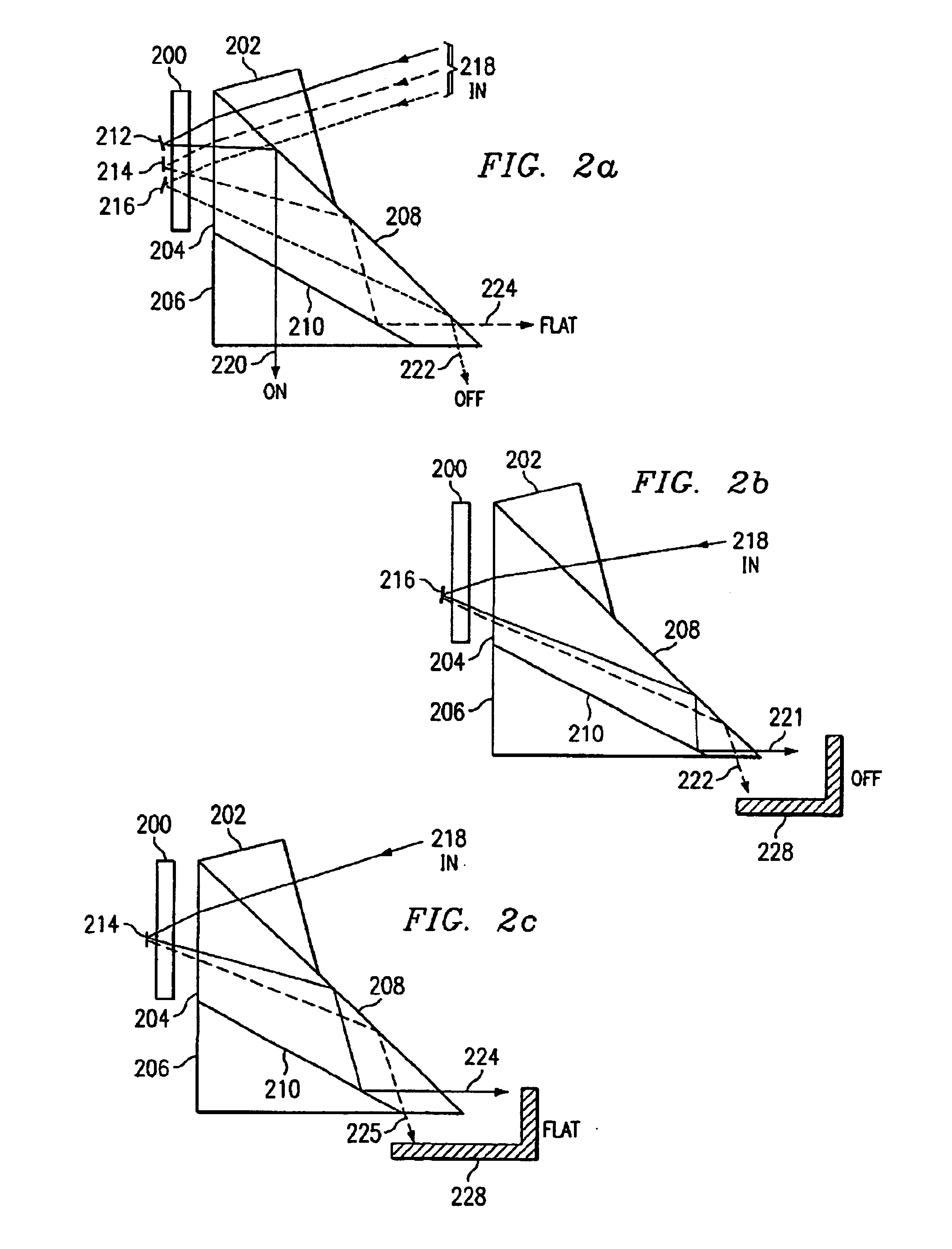
[0029]FIG. 2a is a drawing showing the present invention for a TIR prism assembly, which separates unwanted off-state and flat-state light from the projection ON light bundle in a single SLM projection display system. This configuration consists of a three-element prism coupled to a single SLM 200. Incoming illumination 218 enters through a first prism element 202, which directs light on to the active surface of SLM 200. This first prism 202 is attached to the upper portion of a second larger prism 204, which has a first TIR surface 208 and a second TIR surface 210, for separating and routing the various types of reflected light, coming off the surface of the SLM, out of the prism assembly without contaminating the desired ON projection light. A third prism 206 is attached to the bottom side of prism 204 to provide an equal optical working distance on the input and output side of the projection cone for the ON pixel projection light.

[0030]In operation, the first prism element 202 di...

third embodiment

[0038]FIG. 4 is a drawing showing the present invention for a TIR prism assembly where unwanted off-state and flat-state light is separated from the projection ON light bundle in a multi-chip [two or more, three shown for red (R), (G), (B)] SLM projection display system. This prism assembly incorporates TIR surfaces 410, 412 as close as possible to the SLM devices 400, 402 to directly receive the unwanted light from the SLMs and direct this light to an optical heat sink (not shown). The assembly consists of prism 406, 408 for getting white light 416 into the system and getting the projected ON light 420 out of the system into a projection lens (not shown) in a display application, a color splitting / recombining prism assembly 404 for splitting the white light 416 into the three R-G-B color beams, and three respective red (R) 402, green (G) 400, and blue (B) (not shown but located on the opposite side of the prism from the red device). The three prism elements have additional TIR surf...

fourth embodiment

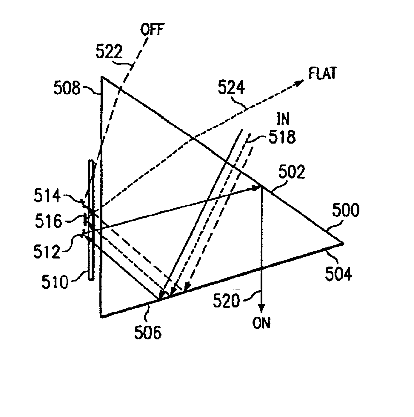
[0041]FIG. 5 is a drawing showing the present invention for a low-cost, single-element TIR prism having two TIR surfaces to separate the unwanted off-state and / or flat-state light from the projection light bundle and route it to an optical heat sink. Although somewhat larger is physical size, a single TIR prism element tends to be lower cost and is therefore attractive in lower end systems where cost may be more important than size. This configuration consists of the single prism, which has a first side 500 with a first TIR surface 502, a second side 504 with a second TIR surface 506, a third side 508, and a SLM deice 510 mounted in close proximity to the third side 508 of the prism. Optionally, as in the earlier cases, the SLM package can be attached directly to the third side 508 of the prism.

[0042]In operation, incoming light 518 enters the through the first side 500 of the prism at an angle greater than the critical angle of the second TIR surface 506 and reflects off this TIR s...


PUM


Abstract

Prism elements having TIR surfaces placed in close proximity to the active area of a SLM device 302 to separate unwanted off-state 324 and/or flat-state 326 light from the projection ON-light bundle 322. The TIR critical angle of these prisms is selected to affect either the off-state light or additionally, any portion of flat-state light reflected from the SLM. These TIR surfaces are placed to immediately reflect the unwanted light as it comes off the SLM, thereby preventing the contamination of light along the projection path, which tends to degrade the system contrast. To further improve the optical performance of the system, these TIR prisms can be attached directly to the SLM package 300, completely eliminating the package window. Also, these TIR prism can be coupled to DMDs having asymmetric mirrors, which tilt through a larger angle for the ON-light to provide high etendue and lumen output, but through near-zero degrees for the OFF-light, thereby improving the separation of any unwanted light from the off/flat states.

Description

[0001]THIS APPLN CLAIMS BENEFIT OF 60 / 345,732 filed Dec. 31 2001.FIELD OF THE INVENTION[0002]The present invention relates to optical elements used in projection systems and more particularly to high contrast prisms, which separate unwanted light reflected from the OFF pixels from the projection illumination bundle reflected from the ON pixels.BACKGROUND OF THE INVENTION[0003]In a typical spatial light modulator (SLM) projection system, such as a digital micromirror device (DMD) based system, undesired off-state and flat-state light can overlap the desired image projection illumination for some distance along the optical path and is often reflected on to the screen causing a reduction in image contrast. In high power projectors, the off-state light can be of sufficient duration and magnitude to increase the thermal energy in the optics and other hardware, resulting in optical distortion, mechanical stress, and / or image misconvergence.[0004]This unwanted light can result from scatter...

Claims


Application Information

Patent Timeline
Patent Type & Authority Patents(United States)
IPC IPC(8): G02B5/04G02B7/18H04N9/31
CPCG02B5/04G02B7/181H04N9/3105
Inventor PENN, STEVEN M.
Owner TEXAS INSTR INC
Why Eureka
Try Eureka