Directional privacy display

a display and privacy technology, applied in the field of illumination of light modulation devices, can solve the problems of low power operation, disruption, and inability to alter the image content, and achieve the effect of high electrical efficiency and low cos

Active Publication Date: 2015-12-31
REALD SPARK LLC
View PDF3 Cites 75 Cited by
  • Summary
  • Abstract
  • Description
  • Claims
  • Application Information

AI Technical Summary

Benefits of technology

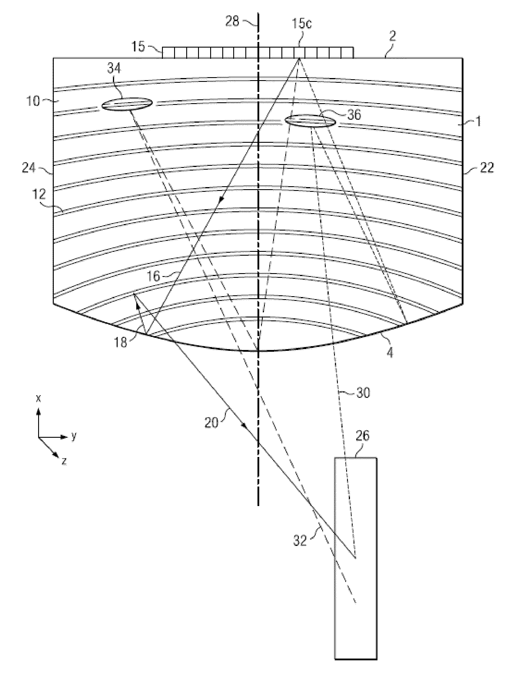
[0007]Thus a display may provide a primary image to a first observer with high luminance and high contrast over a comfortable viewing range. A secondary observer outside the viewing range may observe a secondary image with lower luminance than the primary image, and further comprises reduced contrast, disruptive pattern or other obscuration effects. Advantageously, the desired primary image may difficult to perceive by the secondary observer, thus improving the security of use of the display in public environments. Further, reflections from the display surface may further obscure the image to the secondary observer. Such a display may be arranged to switch between a wide angle viewing mode and a privacy mode. Further such a display may achieve low power operation for extended time between battery charges. Very high luminance mode may be provided over a reduced angular range for substantially the same power consumption as wide angle mode operation. Further, such a display may be arranged to achieve autostereoscopic display operation.
[0013]Advantageously the obscuration effect may combine reduced luminance, reduced contrast and disruptive image content that may be dependent on the primary image content to provide further obscuration in regions where the cancelling of the primary and secondary images are not complete due to angular variations of the contrast of the spatial light modulator.
[0017]Advantageously leakage of secondary image into the primary image may be reduced, for example to reduce the appearance of disruptive patterns from the secondary image in the primary image for the primary observer.
[0021]Advantageously a high luminance, high efficiency and com pact backlight may be provided for a directional privacy display. By means of control of an array of light sources, such a backlight may achieve controllable modes of operation including low power, high luminance, autostereoscopic and privacy operation.
[0024]Advantageously the freedom of movement for the primary viewer may be increased, and the range over which a secondary observer may attempt to see the primary image may be reduced.
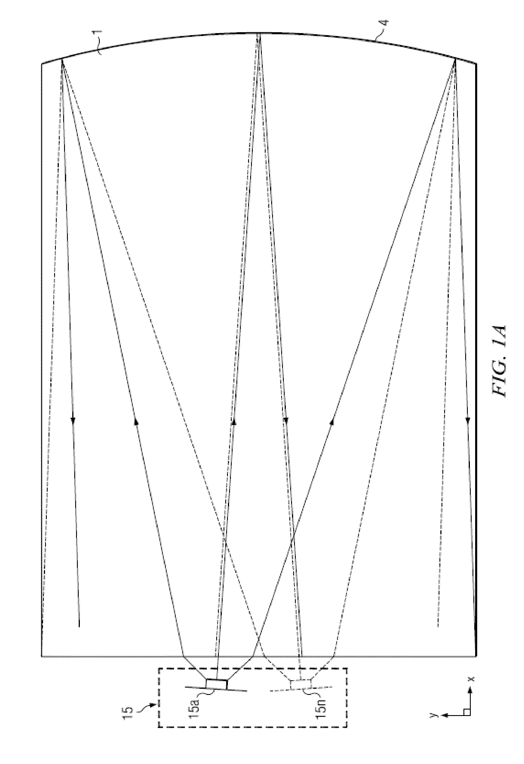
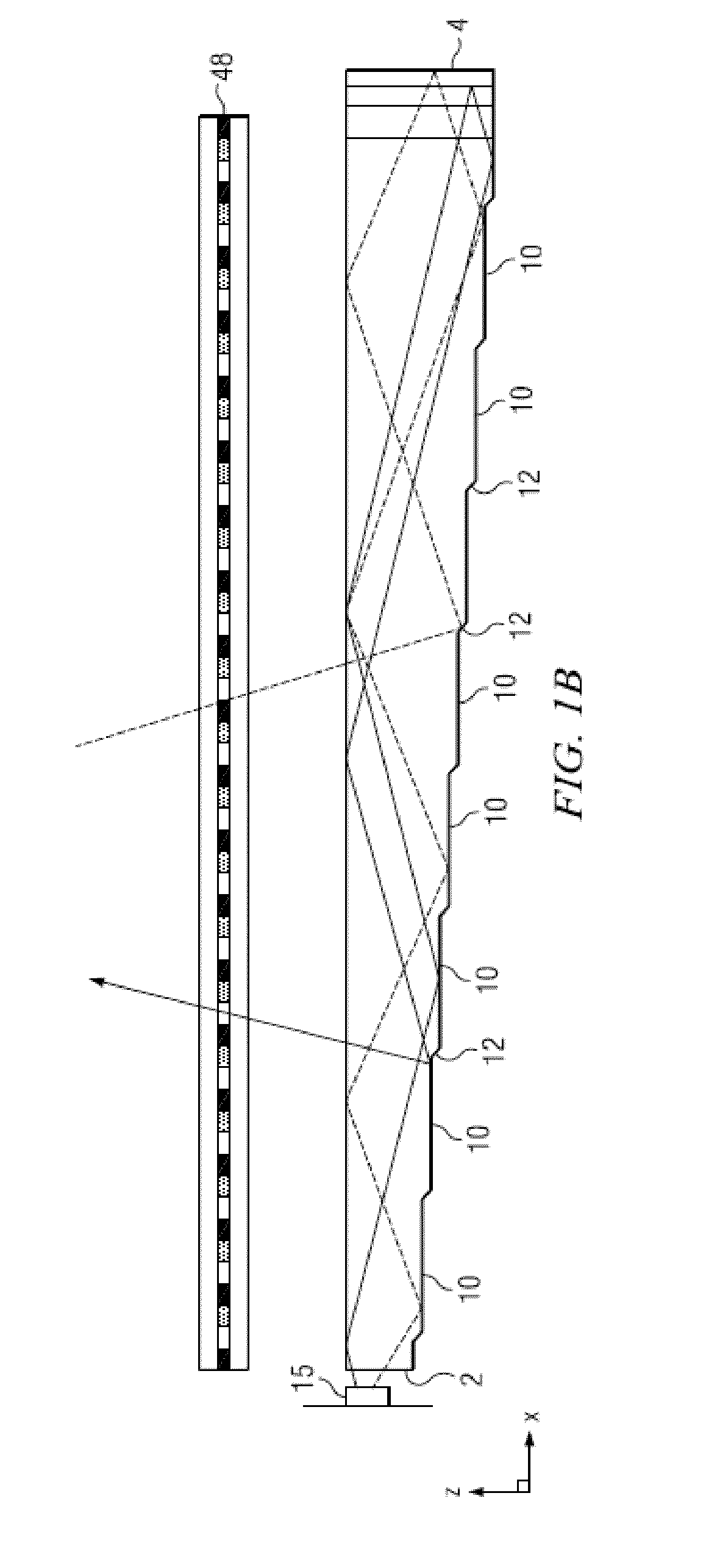
[0030]Directional backlights offer control over the illumination emanating from substantially the entire output surface controlled typically through modulation of independent LED light sources arranged at the input aperture side of an optical waveguide. Controlling the emitted light directional distribution can achieve single person viewing for a security function, where the display can only be seen by a single viewer from a limited range of angles; high electrical efficiency, where illumination may be provided over a small angular directional distribution; alternating left and right eye viewing for time sequential stereoscopic and autostereoscopic display; and low cost.

Problems solved by technology

Advantageously, the desired primary image may difficult to perceive by the secondary observer, thus improving the security of use of the display in public environments.
Further, reflections from the display surface may further obscure the image to the secondary observer.
Further such a display may achieve low power operation for extended time between battery charges.
Such disruption may be achieved without altering the image content and may be time varying.

Method used


Image

  • Directional privacy display
  • Directional privacy display
  • Directional privacy display

Examples


Embodiment Construction

[0094]Time multiplexed autostereoscopic displays can advantageously improve the spatial resolution of an autostereoscopic display by directing light from all of the pixels of a spatial light modulator to a first viewing window in a first time slot, and all of the pixels to a second viewing window in a second time slot. Thus an observer with eyes arranged to receive light in first and second viewing windows will see a full resolution image across the whole of the display over multiple time slots. Time multiplexed displays can advantageously achieve directional illumination by directing an illuminator array through a substantially transparent time multiplexed spatial light modulator using directional optical elements, wherein the directional optical elements substantially form an image of the illuminator array in the window plane.

[0095]The uniformity of the viewing windows may be advantageously independent of the arrangement of pixels in the spatial light modulator. Advantageously, su...


PUM


Abstract

A directional privacy display may include a waveguide; and an array of light sources and spatial light modulator that operate in a time sequential manner. The waveguide may include light extraction features arranged to direct light from an array of light sources by total internal reflection to an array of viewing windows and a reflector arranged to direct light from the waveguide by transmission through extraction features of the waveguide to the same array of viewing windows. First and second phases may be temporally multiplexed with respective primary and secondary images and primary and secondary angular illumination distributions. An efficient and bright privacy display may be provided with obscured primary image visibility for off-axis observers.

Description

CROSS-REFERENCE AND PRIORITY CLAIM TO RELATED APPLICATIONS[0001]This application is related to U.S. patent application Ser. No. 13 / 300,293, “Directional flat illuminators,” filed Nov. 18, 2011, (Attorney Ref. No. 95194936.281001), U.S. patent application Ser. No. 13 / 836,443, “Crosstalk suppression in a directional backlight,” filed Mar. 15, 2013 (Attorney Ref. No. 95194936.317001), U.S. patent application Ser. No. 14 / 186,862, “Directional backlight,” filed Feb. 21, 2014, (Attorney Ref. No. 95194936.355001), U.S. Provisional Patent Application No. 62 / 167,203, entitled “Wide angle imaging directional backlights,” filed May 27, 2015, (Attorney Ref. No. 384000), U.S. Patent Provisional Application No. 62 / 167,185, entitled “Wide angle imaging directional backlights,” filed May 27, 2015, (Attorney Ref. No. 379000B), all of which are incorporated herein by reference in their entireties. Additionally, this application is related to and claims priority to U.S. Provisional Patent Application ...

Claims


Application Information

Patent Timeline
Patent Type & Authority Applications(United States)
IPC IPC(8): F21V8/00G02B27/22G02B30/33
CPCG02B6/0048G02B27/225G02B6/0068G02B6/0055H04N2013/405G02F1/1323H04N13/32G02B30/33
Inventor ROBINSON, MICHAEL G.WOODGATE, GRAHAM J.HARROLD, JONATHAN
Owner REALD SPARK LLC
Why Eureka
Try Eureka