Display system

a display system and display technology, applied in the field of display systems, can solve the problems of increased electrical energy, economic drawback, additional heat generation, etc., and achieve the effect of reducing and increasing the cost of construction

Inactive Publication Date: 2001-01-02
DAKTRONICS
View PDF1 Cites 161 Cited by
  • Summary
  • Abstract
  • Description
  • Claims
  • Application Information

AI Technical Summary

Problems solved by technology

A solution to these deficiencies called for an increase in power to try to compensate for lack of brilliance or contrast, such solution often incurring extra required electrical energy, an economic drawback, and additional generation of heat.
Along with larger electr...

Method used


Image

  • Display system
  • Display system
  • Display system

Examples


Embodiment Construction

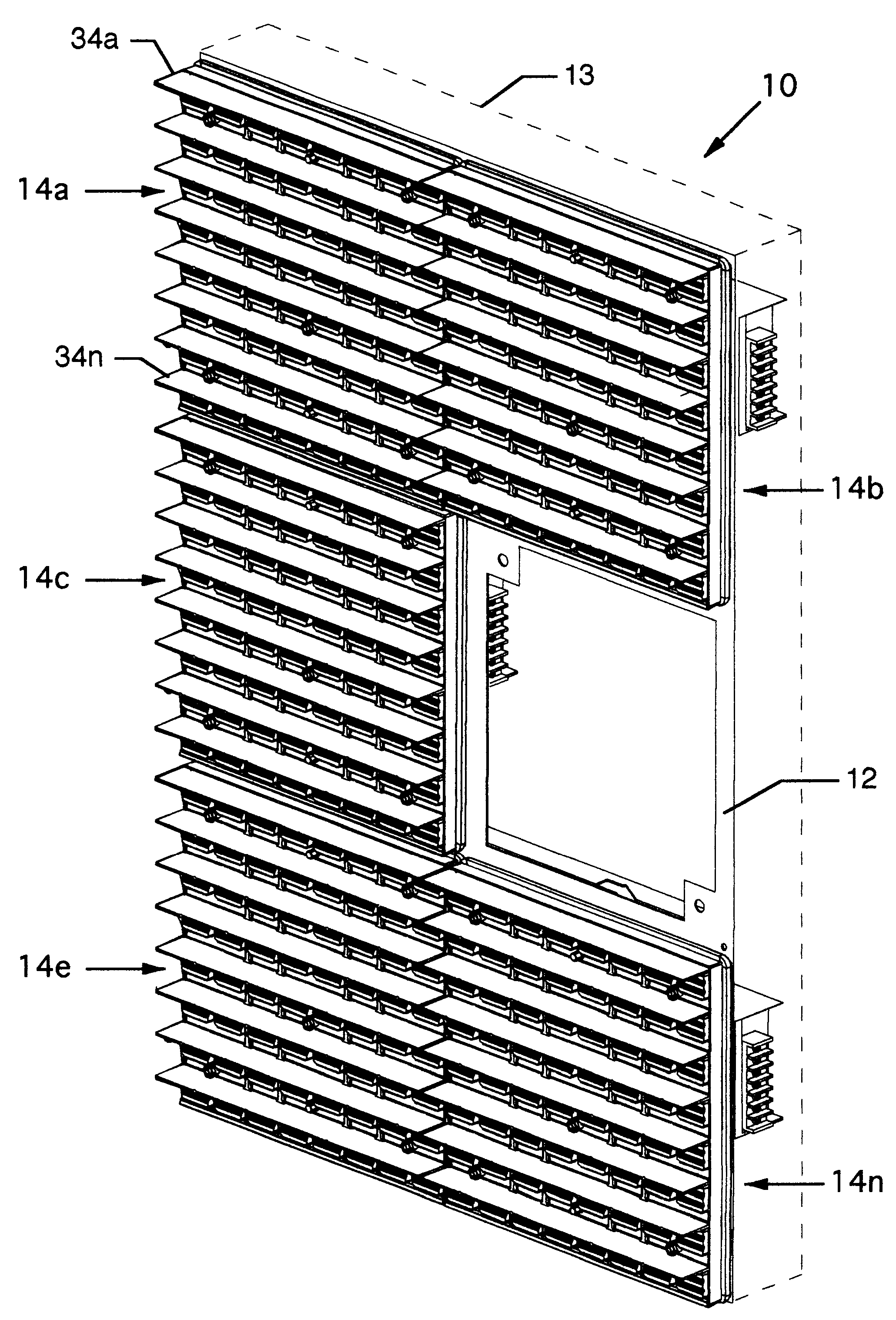
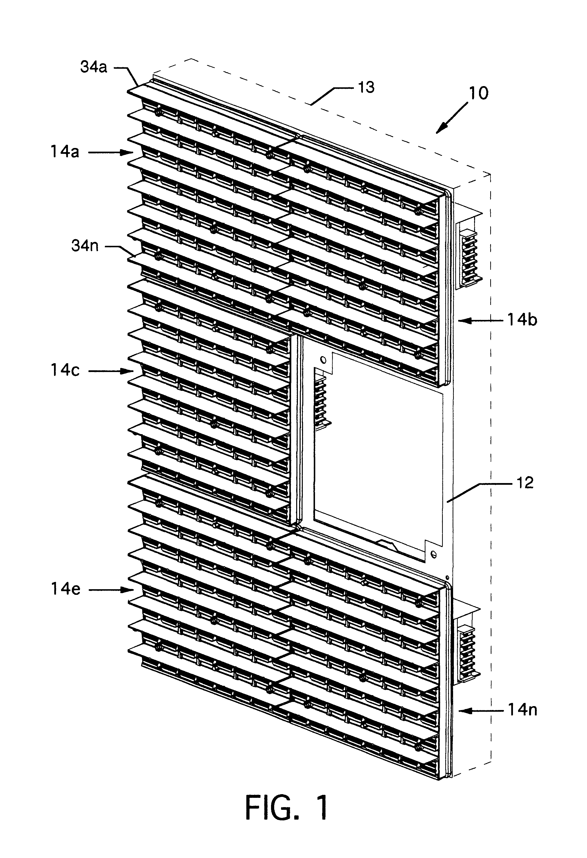
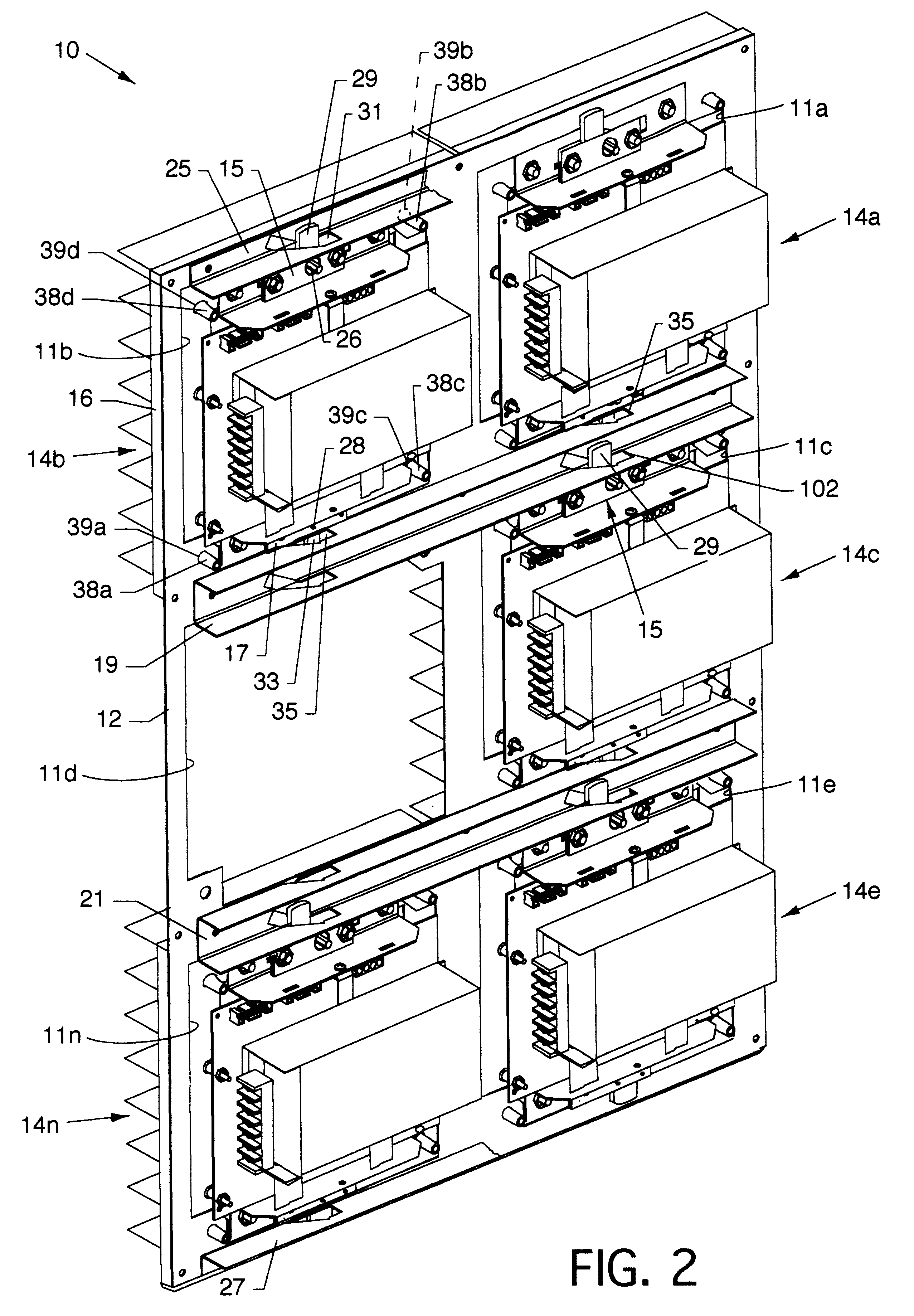
Modular display panels 14a-14n are assembled for subsequent attachment to the module mounting panel 12. At the front of the modular display panels 14a-14n, the printed circuit board 18, containing the LED pixels 20a-20n, is brought into engagement with the housing 16. Pixel lenses 32a-32n are snap fit to the louver panel 24. The louver panel 24, containing the pixel lenses 32a-32n, is then aligned to the housing 16 having the printed circuit board 18 and LED pixels 20a-20n, thereby placing the pixel lenses 32a-32n in close alignment with the LED pixels 20a-20n. At the rear of the modular display panels 14a-14n, upper and lower rails 68 and 70, upper and lower latch assemblies 15 and 17, and the driver card 40, are secured thereto by twist-on removable fasteners, and the power supply is also mounted. Assembled modular display panels 14a-14n are aligned to the mounting posts of the module mounting panel 12 and secured thereto by the actuating of latches 29 and 33 by a nut driver appli...


PUM


Abstract

Modular display system having LED pixels and lenses aligned to the LED's to increase intensity, increase view angle and increase overall viewability. Louvers align along the LED's and lenses to shade the LED's and lenses from ambient light to increase viewability. Modular display panels which contain the LED's, lenses, louvers and other associated components are accessible from the front and back for changeover or repair.

Description

1. Field of the InventionThe present invention is for a display system, and more particularly, pertains to a display system having maintenance accessibility and incorporating LED pixels, lenses, and louvers incorporated into one or more modular display panels to present an electronic display.2. Description of the Prior ArtPrior art electronic display systems oftentimes lacked in brilliance and contrast. A solution to these deficiencies called for an increase in power to try to compensate for lack of brilliance or contrast, such solution often incurring extra required electrical energy, an economic drawback, and additional generation of heat. Along with larger electrical power requirements and heat generation came the need for more heavily constructed components, also an economic drawback. Prior art display systems also provided systems which had poor. access for maintenance in that accessibility was limited to one side of the system. Such accessibility required that numerous fastene...

Claims


Application Information

Patent Timeline
IPC IPC(8): G09F9/33
CPCG09F9/33G09F27/008G09F9/3026Y10S345/903
Inventor KURTENBACH, REECE A.LUTZ, ROBERT JAMESSEELEY, ROBERT E.WENDLER, BRETT DAVID
Owner DAKTRONICS
Why Eureka
Try Eureka