Novel miniature phalanx lengthening device for hand and foot surgery department

An extension device, hand and foot technology, applied in the field of new miniature phalanx extension device for hand and foot surgery, can solve the problems of easy deformation of phalanx, instability of phalanx extension process, secondary trauma of affected area, etc.

Active Publication Date: 2021-12-03
XIAN HONGHUI HOSPITAL
View PDF18 Cites 0 Cited by
  • Summary
  • Abstract
  • Description
  • Claims
  • Application Information

AI Technical Summary

Problems solved by technology

[0003] However, the phalanx extension device in the prior art cannot adopt adaptive fixation measures for the phalanx and the pulp of the finger. The phalanx extension process is unstable and the phalanx is easily deformed when extended, and it is troublesome to disassemble from the affected area, which is easy to cause damage to the affected area due to improper force. secondary trauma; so the present invention provides a novel hand and foot surgery miniature phalanx extension device to solve the above problems

Method used


Image

  • Novel miniature phalanx lengthening device for hand and foot surgery department
  • Novel miniature phalanx lengthening device for hand and foot surgery department
  • Novel miniature phalanx lengthening device for hand and foot surgery department

Examples


Embodiment 1

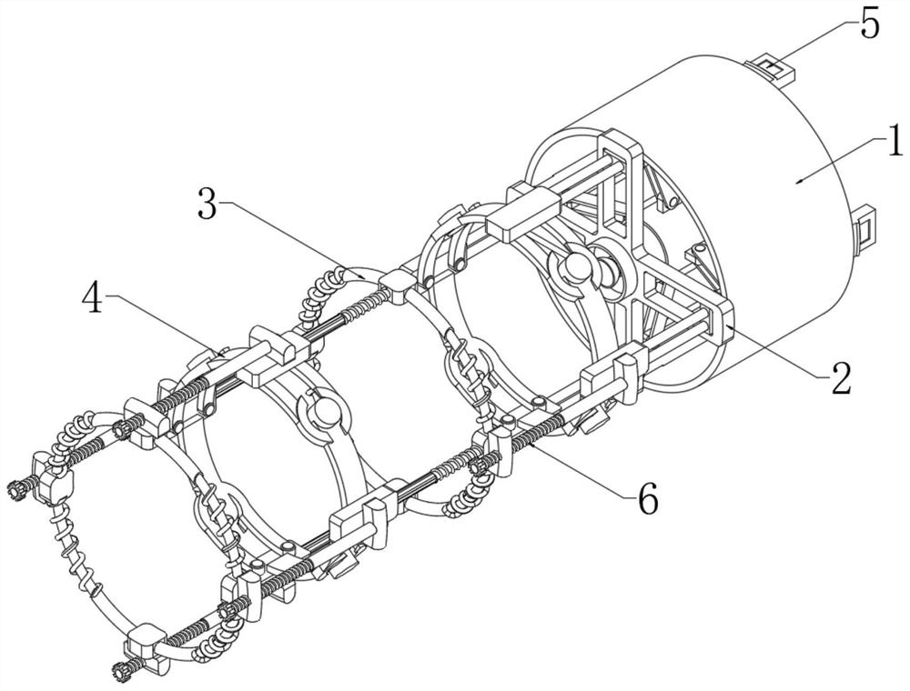
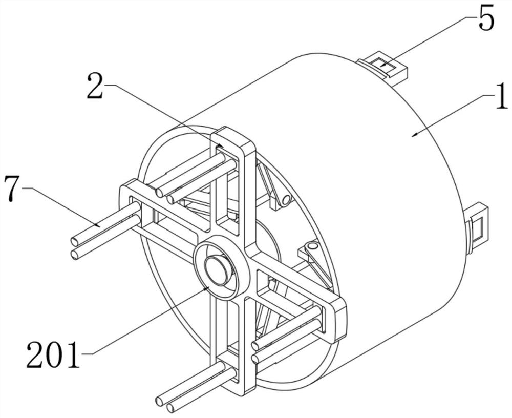
[0037] see Figure 1-6, a new type of miniature phalanx extension device for hand and foot surgery, comprising a hollow cylinder 1, an expansion assembly 5 is arranged inside the hollow cylinder 1, the expansion assembly 5 penetrates the hollow cylinder 1 and is connected with an extension frame 2, and the extension frame 2 and the hollow cylinder 1 One side connection; the expansion assembly 5 runs through the extension frame 2 and is connected with the adjustment assembly 3 and the holding assembly 4, and the adjacent adjustment assembly 3 and the holding assembly 4 are movably connected through the connecting assembly 6; the holding assembly 4 and the adjustment assembly located in the center 3 are connected by an elastic telescopic rod 8, and the external movable sleeve of the elastic telescopic rod 8 is provided with a spring member C9;

[0038] The extension frame 2 is provided with four limit chutes, and the inner slider 204 is slidably connected to the limit chute; the...

Embodiment 2

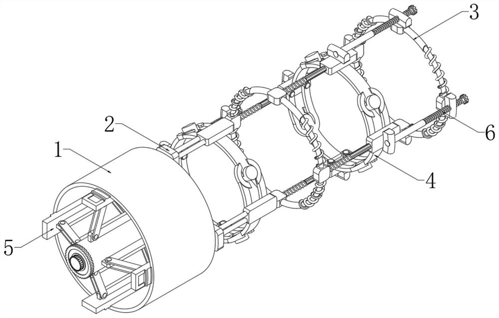
[0045] Such as Figure 7-11 As shown, the differences based on Embodiment 1 are:

[0046] The clamping assembly 4 includes a clamping block A401 and a clamping block B402, and the clamping block A401 and the clamping block B402 are arranged at intervals; a clamping part 404 and a positioning part 403 are arranged between the adjacent clamping blocks A401 and the clamping block B402 , the four groups of clamping parts 404 and the positioning parts 403 are connected end to end;

[0047] The clamping part 404 includes two clamping rods, the clamping rods are respectively connected to the inner sides of the clamping block A401 and the clamping block B402 through the rotating column 406, and the front end of the clamping rod is provided with a magnetic suction arc block; The inner side of the tight block A401 and the tight block B402 are fixedly connected, the end of the positioning piece 403 is fixedly connected with the central column 405, and the magnetic suction arc block is m...

Embodiment 3

[0052] Such as Figure 8-10 As shown, based on embodiment 1-2, what is different is:

[0053] The adjacent adjustment block A301 and the holding block A401 are connected by an elastic telescopic rod 8, and the adjacent adjustment block A301 and the holding block A401 are connected by an elastic telescopic rod 8 between the adjacent adjustment block B302 and the holding block B402. Elastic telescopic rod 8 is connected;

[0054] The connection assembly 6 includes a positioning block A601 and a positioning block B604, the positioning block A601 is fixedly connected to the outside of the holding block A401 or the holding block B402, the positioning block B604 is fixedly connected to the outside of the adjusting block A301 or the adjusting block B302; the center of the adjusting block A301 is fixedly connected There is a threaded pipe 602, the front end of the threaded pipe 602 is threaded with a threaded inner rod 603, the threaded inner rod 603 is threaded in the center of the ...


PUM


Abstract

The invention discloses a novel miniature phalanx lengthening device for the hand and foot surgery department, and belongs to the technical field of surgical equipment. The novel miniature phalanx lengtheningdevice for the hand and foot surgery department comprises a hollow column body, an extension assembly is arranged in the hollow column body, and the extension assembly penetrates through the hollow column body and is connected with an extension frame; the extension assemblies penetrate through the extension frame and are connected with adjusting assemblies and holding assemblies, and the adjacent adjusting assemblies and holding assemblies are movably connected through connecting assemblies. The holding assembly located in the center and the adjusting assembly are connected through an elastic telescopic rod, and the outer part of the elastic telescopic rod is movably sleeved with a spring piece C; four limiting sliding grooves are formed in the extension frame, and inner sliding blocks are connected into the limiting sliding grooves in a sliding mode. The phalanx lengthening device solves the problems that an existing phalanx lengthening device cannot adopt adaptive fixing measures on the knuckles and the finger pulps and is troublesome to detach from the affected part, and secondary trauma is easily caused to the affected part due to improper force application.

Description

technical field [0001] The invention belongs to the technical field of surgical equipment, and in particular relates to a novel miniature phalanx extension device for hand and foot surgery. Background technique [0002] Bone elongation, that is, distraction osteogenesis, is to cut the bone, retain the soft tissue and blood supply, fix the two ends with a special traction device, apply the tension stress law to gradually apply tension to slowly pull the bone segment, continuously stimulate the body tissue, and stimulate the bone segment. The regenerative potential of human tissue enables the formation of new bone in the osteotomy gap to achieve the purpose of bone regeneration. When the phalanx is shortened due to trauma or congenital reasons, the phalanx needs to be extended to make the shortened phalanx reach the normal length. [0003] However, the phalanx extension device in the prior art cannot adopt adaptive fixation measures for the phalanx and the pulp of the finger. ...

Claims


Application Information

Patent Timeline
Patent Type & Authority Applications(China)
IPC IPC(8): A61B17/66A61F5/042
CPCA61B17/66A61F5/042Y02A50/30
Inventor 夏雷
Owner XIAN HONGHUI HOSPITAL
Why Eureka
Try Eureka