Keyway machining jig for motor core

A technology of iron core and keyway, applied in the direction of manufacturing tools, metal processing equipment, metal processing machinery parts, etc., can solve the problems of affecting work efficiency and inconvenient actual operation

Active Publication Date: 2022-03-15
常州翱隆新能源电机有限公司
View PDF6 Cites 0 Cited by
  • Summary
  • Abstract
  • Description
  • Claims
  • Application Information

AI Technical Summary

Problems solved by technology

[0004] In view of the above situation, in order to overcome the defects of the prior art, the present invention provides a keyway processing jig for the motor iron core, which effectively solves the need for multiple manual operations to clamp the iron core body in the above background technology, and the actual operation is relatively inconvenient. Problems affecting work efficiency

Method used


Image

  • Keyway machining jig for motor core
  • Keyway machining jig for motor core
  • Keyway machining jig for motor core

Examples


Embodiment 1

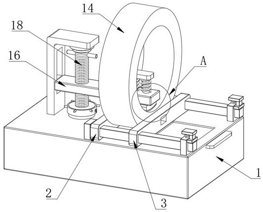
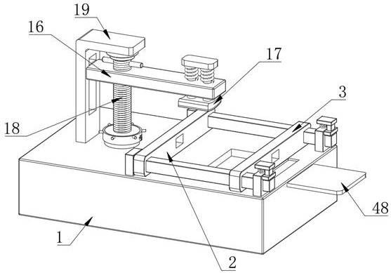
[0035] Embodiment one, by Figure 1 to Figure 9 Given, the present invention comprises a control box body 1, the top of the control box body 1 is provided with a fixed clamping plate 2 and a movable clamping plate 3, the top inner wall of the control box body 1 is provided with a positioning hole 4, and the top of the control box body 1 The inner wall is provided with a first rectangular hole 5, the control box body 1 is provided with a movable adjustment plate 6, and the top of the movable adjustment plate 6 extends into the first rectangular hole 5, and the control box body 1 is provided with a first threaded rotating column 15, The first threaded rotating column 15 runs through the movable adjustment plate 6, and the connection mode between the first threaded rotating column 15 and the movable adjusting plate 6 is threaded connection, and the control box body 1 is provided with a drive unit that matches the first threaded rotating column 15, The top of the movable adjustmen...

Embodiment 2

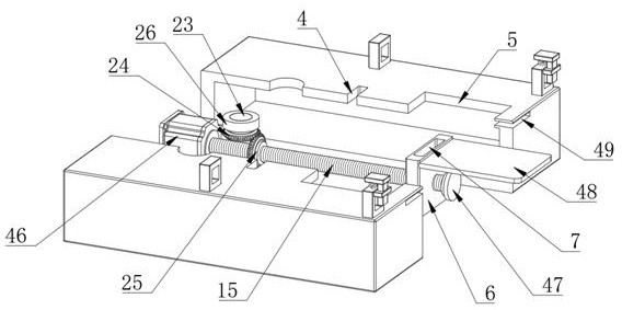
[0037] Embodiment two, on the basis of embodiment one, by image 3 , Figure 4 , Figure 6 , Figure 7 with Figure 8 Given, the engagement adjustment assembly includes a rotating shaft 23 disposed below the second threaded rotating column 18, the rotating shaft 23 runs through the top inner wall of the control box body 1, and the rotating shaft 23 is connected to the penetration of the control box body 1 through a second bearing 26 , and the bottom of the rotating shaft 23 is fixedly connected with the first bevel gear 24 located in the control box body 1, and the outside of the first threaded rotating column 15 is provided with a second bevel gear 25, and the second bevel gear 25 is connected to the first bevel gear. A threaded rotating column 15 is fixedly connected, and the first bevel gear 24 and the second bevel gear 25 are meshed, the bottom of the second threaded rotating column 18 is fixedly connected with a fixed plate 28, and the top of the rotating shaft 23 is f...

Embodiment 3

[0039] Embodiment three, on the basis of embodiment two, by Figure 6 , Figure 7 with Figure 8Given, the anti-rotation assembly includes a movable ring 27 sleeved on the outside of the second threaded rotating column 18, a positioning tube 29 is sleeved outside the movable ring 27, and the positioning tube 29 is fixedly connected with the movable ring 27, and the inner wall of the positioning tube 29 Two first grooves 30 are provided, the first groove 30 is provided with a first limiting column 31, and the fixed plate 28 is provided with two second grooves 32, and one end of the first limiting column 31 is located on the second In the groove 32, and one end of the first limiting post 31 is connected to the inner wall of one side of the second groove 32 through a compression spring 33, and a pressing plate 34 is arranged in the first groove 30, and one side of the pressing plate 34 is fixedly connected There is a pressing column 35, and one end of the pressing column 35 run...


PUM


Abstract

The invention relates to the technical field of motor production and processing, and discloses a keyway processing fixture for a motor iron core, which solves the problems that manual operations are required to clamp the iron core body many times, the actual operation is relatively inconvenient, and the work efficiency is affected. The box body, the top of the control box body is provided with a fixed clamping plate and a movable clamping plate, the top inner wall of the control box body is provided with a positioning hole, and the top inner wall of the control box body is provided with a first rectangular hole. There is a movable adjustment plate, the top of the movable adjustment plate extends into the first rectangular hole, the control box body is provided with a first threaded rotation column, the first threaded rotation column penetrates the movable adjustment plate, the first threaded rotation column and the movable adjustment plate The connection method is screw connection; the lifting adjustment plate and the movable clamping plate can be driven to move at the same time, thereby completing the fixing of different positions of the iron core body, improving the stability of the clamping and improving the clamping efficiency.

Description

technical field [0001] The invention belongs to the technical field of motor production and processing, in particular to a keyway processing jig for motor iron cores. Background technique [0002] During the production and processing of the motor, it is usually necessary to open a keyway for the motor core so that it can be connected with the casing. During the processing of the keyway, the iron core of the motor must be fastened and fixed to prevent the position of the keyway from deviating or the width of the keyway from not meeting the design expectation, which will affect its assembly accuracy. However, in the prior art, clamps are used to clamp and fix both sides of the fixed iron core when machining the keyway, and the iron core may deviate in the radial direction during the machining process, thereby affecting the machining accuracy. At the same time, the existing tooling needs to surround the whole, resulting in larger volume and heavier weight of the tooling, high ...

Claims


Application Information

Patent Timeline
Patent Type & Authority Patents(China)
IPC IPC(8): B23Q3/00
CPCB23Q3/00B23Q2703/10
Inventor 林杰
Owner 常州翱隆新能源电机有限公司
Why Eureka
Try Eureka