A diffractive optical waveguide display device

A display device, a technology of diffracting light, applied in the direction of light guide, flat/plate light guide, light guide of lighting system, etc., can solve the problems of low ACR, waste of s-polarized light, etc., achieve high ambient light contrast, improve clarity, improve Image source sharpness effect

Active Publication Date: 2022-04-08
NANCHANG VIRTUAL REALITY RES INST CO LTD
View PDF6 Cites 0 Cited by
  • Summary
  • Abstract
  • Description
  • Claims
  • Application Information

AI Technical Summary

Problems solved by technology

) This will lead to the fact that when PDLC-VHG is matched with an image source that emits unpolarized light such as a micron light-emitting diode, only p-polarized light is coupled into the optical waveguide and then coupled out into the human eye, while most of the s-polarized light is directly transmitted by the waste (such as image 3 ), resulting in a lower ACR

Method used


Image

  • A diffractive optical waveguide display device
  • A diffractive optical waveguide display device
  • A diffractive optical waveguide display device

Examples


experiment example

[0063] This experimental example adopts the diffraction grating in the present invention, that is, PDLCC-VHG.

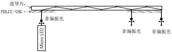
[0064] A diffractive optical waveguide device, including a Micro-LED image source, a PDLCC-VHG coupling grating, a PDLCC-VHG coupling grating, and a waveguide plate.

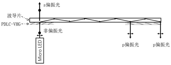
[0065] like figure 1 As shown, the image displayed by the Micro-LED image source is coupled into the waveguide plate through the PDLCC-VHG at the incident end, and the coupled light brightness is 1200 nit. Out of the waveguide.

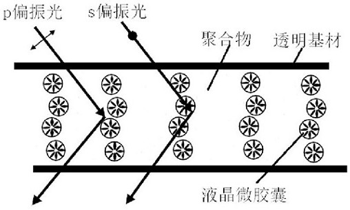
[0066] The thickness of the PDLCC-VHG used is 10 μm, the grating period is 800 nm, the refractive index of the polymer matrix is ​​1.50, the inner diameter of the liquid crystal microcapsule is 30 nm, the shell thickness is 10 nm, and the shell material is alternating The linked polyacrylate, liquid crystal is THT-2.

[0067] The diffraction efficiencies of PDLCC-VHG for s-polarized and p-polarized light are 88% and 89%, respectively.

[0068] Since the grating has differ...


PUM

PropertyMeasurementUnit
thicknessaaaaaaaaaa
thicknessaaaaaaaaaa
grating periodaaaaaaaaaa

Abstract

The invention belongs to the field of AR optical waveguide display, and specifically relates to a diffractive optical waveguide display device, which includes a diffraction grating, a waveguide plate is arranged on one side of the diffraction grating, an image source is arranged on the other side of the diffraction grating, and the image source is The emitted light beam passes through the diffraction grating and enters into the waveguide plate. The diffraction grating includes periodically distributed liquid crystal microcapsules. The liquid crystal microcapsules are hollow spherical with an inner diameter of 10-60 nm and a surface thickness of 5-5 nm 30 nm, the liquid crystal microcapsules are used to increase the diffraction rate of s-polarized light and p-polarized light, so that both s-polarized light and p-polarized light can be totally reflected in the waveguide plate, so as to improve the output image of the waveguide plate The role of clarity. The technology provided by the invention can intuitively, concretely and numerically improve the definition of the image source, and also has advantages in terms of maximum brightness, resolution, ambient light contrast, energy consumption, service life, response speed and thermal stability. .

Description

technical field [0001] The invention belongs to the field of AR optical waveguide display, and in particular relates to a diffractive optical waveguide display device. Background technique [0002] Optical waveguide display technology is an important development direction in the field of AR. Holographic volume gratings are usually prepared by holographic exposure of photosensitive materials with coherent lasers. Due to their advantages of high diffraction efficiency, low cost, and easy large-scale production, they are expected to be applied to optical waveguide AR displays based on holographic volume gratings. Polymer-dispersed liquid crystal holographic volume grating is a holographic volume grating based on polymer / liquid crystal composite materials. It not only has excellent optical properties, but also has electro-optic responsiveness. It has attracted extensive attention in the industry and is very commercially applied in optical waveguide AR displays. potential. On t...

Claims


Application Information

Patent Timeline
Patent Type & Authority Patents(China)
IPC IPC(8): G02B27/01G02B6/00G02F1/1334G02F1/16757
CPCG02B27/0101G02B6/0016G02F1/1334G02F1/16757
Inventor 倪名立谭志先李建军
Owner NANCHANG VIRTUAL REALITY RES INST CO LTD
Why Eureka
Try Eureka