Cutter clamping equipment for numerical control machine tool

A tool clamping and CNC machine tool technology, which is applied in the field of CNC machine tools, can solve problems such as tool clamping instability, worktable damage, and worktable collision, and achieve the effects of ensuring stability, reducing quality, and preventing tool vibration

Pending Publication Date: 2022-07-15
杨志景
View PDF0 Cites 0 Cited by
  • Summary
  • Abstract
  • Description
  • Claims
  • Application Information

AI Technical Summary

Problems solved by technology

[0003] However, when the current tool clamping equipment clamps the tool, due to the unskilled operation of the staff, the tool clamping will be unstable or the air pump will absorb the tool clamping and the position will shift, which will cause damage to the machine body. In severe cases, the tool will fall and collide with the workbench, causing severe damage to the workbench. Therefore, we propose a tool clamping device for CNC machine tools

Method used


Image

  • Cutter clamping equipment for numerical control machine tool
  • Cutter clamping equipment for numerical control machine tool
  • Cutter clamping equipment for numerical control machine tool

Examples


Embodiment Construction

[0034] The technical solutions in the embodiments of the present invention will be clearly and completely described below with reference to the accompanying drawings in the embodiments of the present invention. Obviously, the described embodiments are only a part of the embodiments of the present invention, rather than all the embodiments. Based on the embodiments of the present invention, all other embodiments obtained by those of ordinary skill in the art without creative efforts shall fall within the protection scope of the present invention.

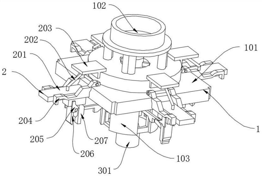
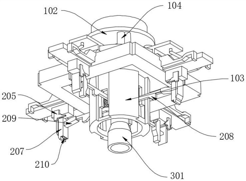
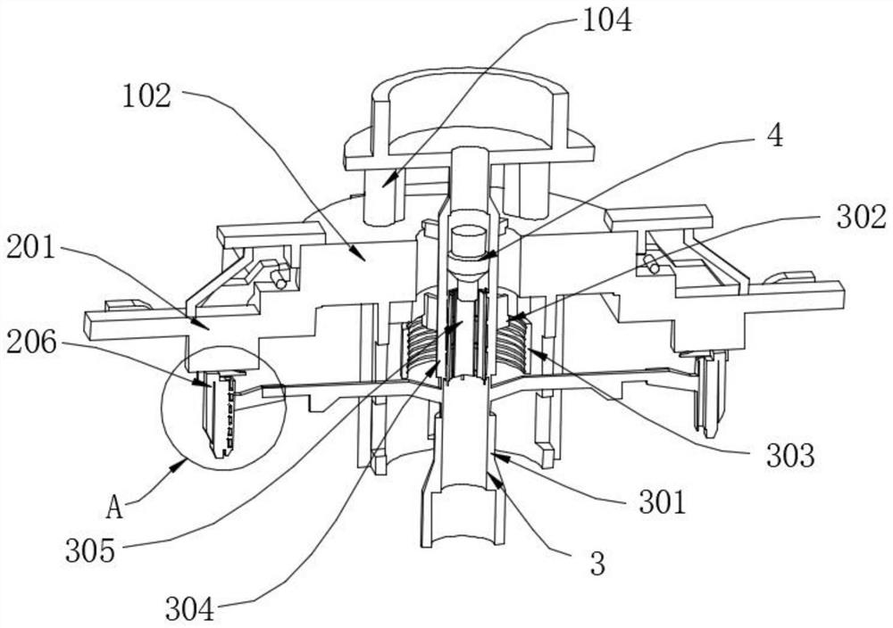
[0035] Refer to the manual attached Figure 1-7, a tool clamping device for CNC machine tools according to an embodiment of the present invention includes a tool clamping mechanism 2 and an anti-vibration knife mechanism 4, the tool clamping mechanism 2 includes a push plate frame 201, and the top of the push plate frame 201 is provided with a rubber clamp The holding rod 202, the outer side of the rubber clamping rod 202 is clamped ...


PUM


Abstract

The invention discloses cutter clamping equipment for a numerical control machine tool, and particularly relates to the field of numerical control machine tools, the cutter clamping equipment comprises a cutter clamping mechanism and a cutter vibration preventing mechanism, the cutter clamping mechanism comprises a push plate frame, a rubber clamping rod is arranged at the top end of the push plate frame, and a limiting plate frame is connected to the outer side of the rubber clamping rod in a clamped mode; clamping plate frames are rotatably connected to the two sides of the push plate frame, a single-side clamping plate is arranged at the bottom end of the push plate frame, rotating rod frames are rotatably connected to the two sides of the single-side clamping plate, the single-side clamping plate and the rotating rod frames are arranged in a limiting state, and when a cutter rotates, an outer side clamping rod drives a threaded push frame to rotate; the thread pushing frame extrudes the air bag at the bottom end of the thread pushing frame, and the air outlet hole of the air bag of the thread pushing frame blows the machined cutter to clean the surface of the cutter, so that the machined cutter is cooled while the surface of the cutter is cleaned, and the service life of the cutter is prolonged.

Description

technical field [0001] The present invention relates to the technical field of numerically controlled machine tools, and more particularly, to a tool clamping device for numerically controlled machine tools. Background technique [0002] CNC machine tool is the abbreviation of digital control machine tool. It is an automatic machine tool equipped with a program control system. The control system can logically process programs with control codes or other symbolic instructions, decode them, and use coded numbers. Indicates that it is input into the numerical control device through the information carrier. After arithmetic processing, various control signals are sent out by the numerical control device to control the action of the machine tool, and the parts are automatically processed according to the shape and size required by the drawing. Among them, the numerical control machine tool has a tool clamping device to clamp the special tool. [0003] However, when the current t...

Claims


Application Information

Patent Timeline
Patent Type & Authority Applications(China)
IPC IPC(8): B23Q3/00
CPCB23Q3/00
Inventor 杨志景
Owner 杨志景
Why Eureka
Try Eureka