Rainbow hologram recorder

A rainbow hologram and recording device technology, applied in the direction of instruments, etc., can solve problems such as limitations

Inactive Publication Date: 2004-06-02
XIAMEN UNIV
View PDF0 Cites 0 Cited by
  • Summary
  • Abstract
  • Description
  • Claims
  • Application Information

AI Technical Summary

Problems solved by technology

However, due to the need for a stable optical platform, working environment and expensive optical components for shooting, this technology is limited in practical applications
Since 1992, some people in the United States, Japan and other countries have proposed the method of realizing the holographic camera system by miniaturizing the overall optical path to achieve practical purposes, but it still cannot solve the complexity of the optical path system device and its own stability.

Method used


Image

  • Rainbow hologram recorder
  • Rainbow hologram recorder
  • Rainbow hologram recorder

Examples


Embodiment Construction

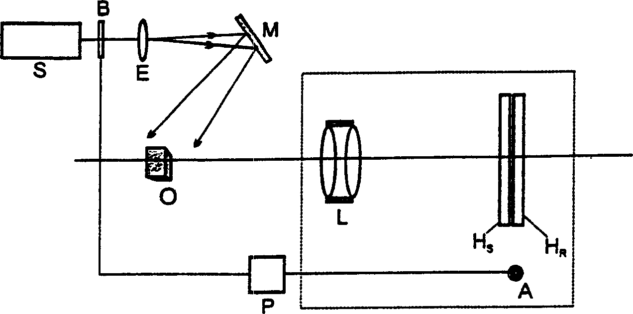
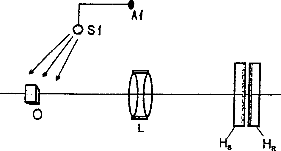
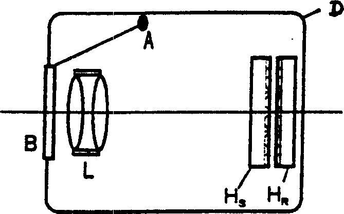
[0014] When the device is shooting, the subject is irradiated by laser light or other light sources with better monochromaticity. figure 1 It shows the whole optical path system when laser is used as light source. The camera part includes imaging lens L, rainbow version H S , Holographic record version H R , shutter button A, that is figure 1 Components included in the dotted box. The difference from ordinary cameras is that the shutter B is placed at the exit of the laser light source to limit the irradiation time of the light on the object O to control the exposure time. The laser light emitted from the laser S is expanded by the beam expander E, and then reflected by the mirror M to the object O. The beam must cover all parts of the object facing the imaging lens L. The centers of the object, the imaging lens, the rainbow plate and the holographic recording plate must be on a straight line, that is, they must be coaxial. Holographic Record Edition H R The plastic sur...


PUM


Abstract

The single beam rainbow hologram recording equipment contains light source, rainbow plate, imaging lens, holographic recording plate and control device, the light source can be laser or other monochromatic light source, and rainbow plate is placed in the imaging position of shot body by means of imaging lens, the film of holographic recording plate is closed to the rainbow plate, the shot body, imaging lens, rainbow plate and holographic recording plate are positioned on same optical axis. It can be used for shooting hologram, after imaged, through exposure and chemical treatment, a white light reproduced rainbow hologram can be obtained. Said equipment is compact in structure, simple and convenient in operation, and possesses extensive application in the holographic interferometric research of nondestructive test, stress and strain analysis and photoelastics.

Description

(1) Technical field [0001] The invention relates to a holographic device, especially a single-beam rainbow hologram recording device obtained by using a laser or a light source with better monochromaticity, a rainbow plate and an imaging lens. (2) Technical background [0002] The previous rainbow hologram recording methods (including one-step method and two-step method) are recorded by two laser beams from the same light source passing through different paths, intersecting at a certain angle on the rubber surface of the holographic recording material, and forming interference fringes. down. In this type of system, a small vibration of any optical element in the recording optical path will seriously damage the interference fringes, resulting in the failure of holographic recording. Therefore, strict anti-vibration measures must be adopted, such as anti-vibration workbench; all optical components, holographic recording materials, recorded objects, etc. must be carefully fixe...

Claims


Application Information

Patent Timeline
Patent Type & Authority Patents(China)
IPC IPC(8): G03H1/04
Inventor 刘守张向苏
Owner XIAMEN UNIV
Why Eureka
Try Eureka