Check patentability & draft patents in minutes with Patsnap Eureka AI!

Method for braking a traction sheave elevator

A technology of elevators and rope pulleys, which is applied to lifting equipment, elevators, transportation and packaging in mines. It can solve the problems of passengers bumping and falling, achieve long service life and expand the application range.

Inactive Publication Date: 2006-01-18
KONE CORP
View PDF0 Cites 0 Cited by
  • Summary
  • Abstract
  • Description
  • Claims
  • Application Information

AI Technical Summary

Problems solved by technology

Depending on the initial deceleration rate, this will cause the passenger to crash into the roof of the elevator or at least fall

Method used


Image

  • Method for braking a traction sheave elevator
  • Method for braking a traction sheave elevator
  • Method for braking a traction sheave elevator

Examples


Embodiment Construction

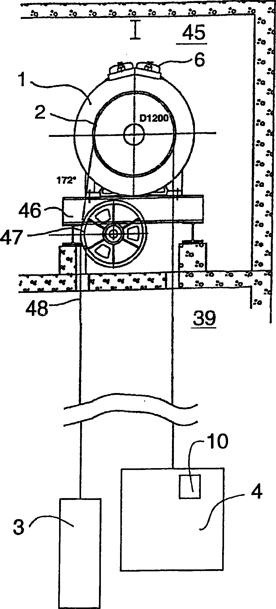
[0018] figure 1 The placement of an elevator drive machine 1 in a machine room 45 above an elevator passage 39 is indicated. The drive machine rests on a mounting base 46 constructed of steel beams. The distance between the sections of hoisting ropes 48 going towards the counterweight 3 and the car has been increased by arranging a diverting pulley 47 so that this distance is slightly greater than the distance corresponding to the diameter of the traction sheave 2 . The brake 6 of the drive machine mainly acts as a hold brake when the elevator is stationary. The preferred method of braking the elevator is electric braking. Generally, in electric braking, the motor brakes in a feedback manner even in the event of a power failure or an emergency stop. The steering brake 6 is engaged to increase the braking force. Thus, the traction sheave is strongly braked, while the ropes, counterweight, car and other masses suspended above them tend to continue their motion. If there is ...


PUM


Abstract

A method for braking a traction sheave elevator stops the elevator in the event of an emergency by the braking of the elevator using a braking device not comprised in the drive machine. A traction sheave elevator is provided with a braking device not comprised in the drive machine and designed to improve the efficiency of emergency stopping. The maximum force decelerating the elevator and generated by the braking device equals about half the weight of the nominal load of the elevator.< / PTEXT>

Description

technical field [0001] The invention relates to a braking method for a traction sheave elevator, to a traction sheave elevator and to the use of an emergency power supply device. Background technique [0002] The machine of a traction sheave elevator comprises a traction sheave with elevator hoisting ropes fitted in its rope grooves and an electric motor driving the traction sheave either directly or via a gear arrangement. The machine is equipped with a brake which applies a braking force to the traction sheave either directly or eg via a shaft. The operating brake of the elevator works under positive control, so that the brake is always on when it is not specifically deactivated by the control system. In a typical actuated brake arrangement, the brake is closed by the force of a spring or equivalent, and a controllable actuator counteracting the closing member releases the brake and keeps it released. When braking is applied to the traction sheave, the braking effect is ...

Claims


Application Information

Patent Timeline
Patent Type & Authority Patents(China)
IPC IPC(8): B66B5/18B66B5/02
CPCB66B15/04B66B5/02B66B5/18
Inventor 塞波·马特拉尔佩蒂里·瓦尔贾斯约翰尼斯·德琼
Owner KONE CORP
Features
  • R&D
  • Intellectual Property
  • Life Sciences
  • Materials
  • Tech Scout
  • Unparalleled Data Quality
  • Higher Quality Content
  • 60% Fewer Hallucinations
Learn More