Electronic gun of single-colour cathode-ray tube with improved structure

A cathode ray tube and structure improvement technology, applied in the field of electron guns, can solve problems such as insufficient brightness and chroma, electron beam adjustment, and expansion of electron beam cross-sectional area, achieve good resolution and focus quality, improve screen brightness, and reduce current load effect

Inactive Publication Date: 2006-10-25
CHUNGHWA PICTURE TUBES LTD
View PDF0 Cites 0 Cited by
  • Summary
  • Abstract
  • Description
  • Claims
  • Application Information

AI Technical Summary

Problems solved by technology

Although this approach can effectively improve the problems of insufficient brightness and chroma, yet, applying a large current to the single electron current emission source of each monochrome cathode ray tube will reduce the number of electrons in the single electron beam produced. Due to the mutual repulsion of the charges, the cross-sectional area of ​​the electron beam gradually expands along the screen direction of each monochrome cathode ray tube, and even the halo worsens. Although this phenomenon can be adjusted by adjusting each The design of the focusing lens or the common lens in the electron gun of the monochromatic cathode ray tube with the improved structure, or by enlarging or deepening the inner diameter of the neck of each of the monochromatic cathode ray tubes, can be slightly improved, but due to the inner diameter of the glass neck There is a certain specification limitation, so due to this limitation, the main lens of the electron gun cannot be expanded infinitely. Therefore, the cross-sectional area of ​​the electron beam cannot be adjusted to an ideal size. This is the front or rear projection type for many years. The image resolution and focus quality of cathode ray tube projection TVs have not been effectively improved, and are the main causes of human fouling

Method used


Image

  • Electronic gun of single-colour cathode-ray tube with improved structure
  • Electronic gun of single-colour cathode-ray tube with improved structure
  • Electronic gun of single-colour cathode-ray tube with improved structure

Examples


Embodiment Construction

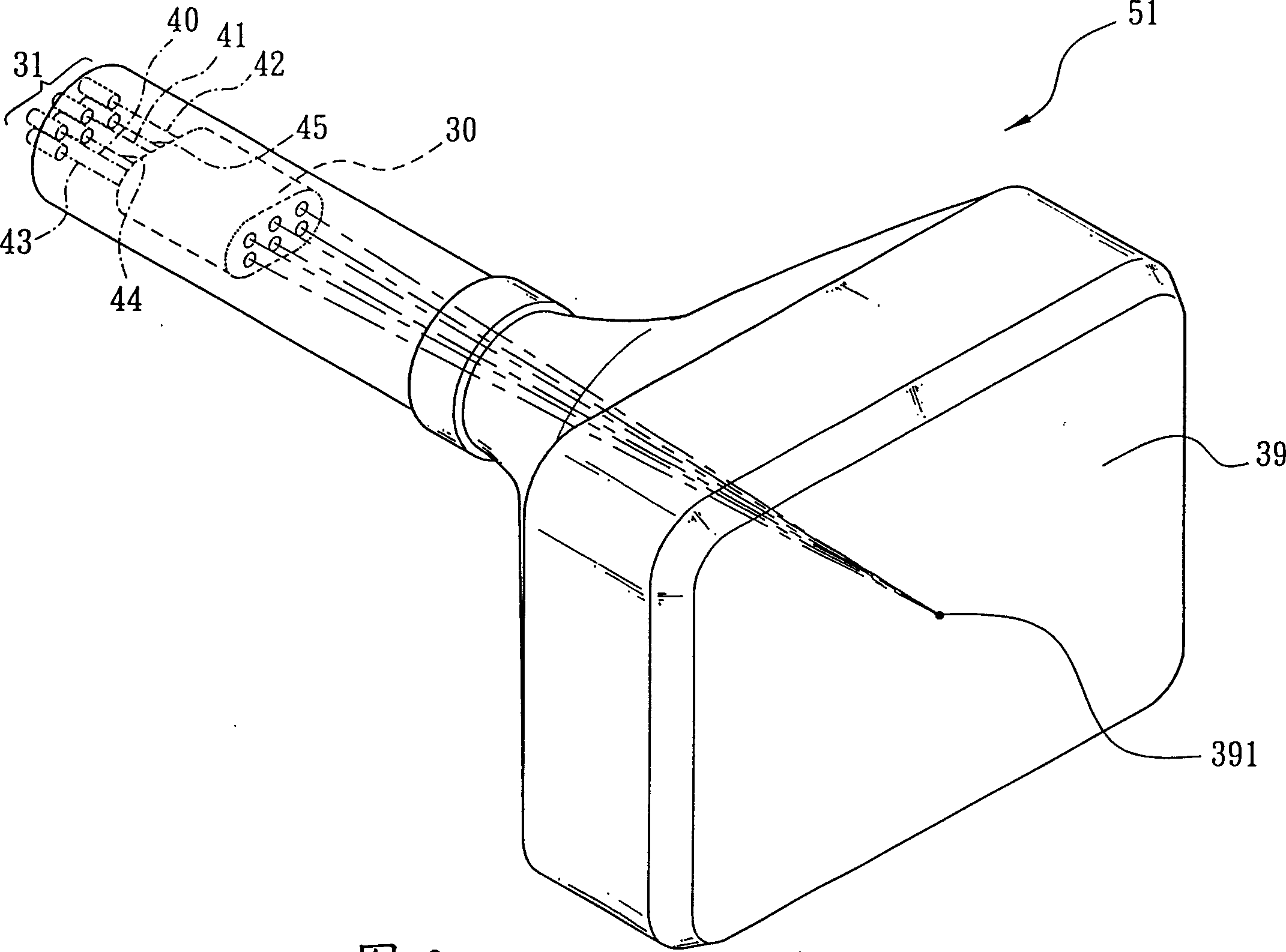
[0034] The invention is an electron gun of a monochromatic cathode ray tube with improved structure, and the monochromatic cathode ray tube is a monochromatic cathode ray tube which can be used in a projection TV to produce red, green or blue tone images The electron gun of the monochromatic cathode ray tube with improved structure can be designed to have at least two electron current emission sources (such as: cathode or other carbon nanotubes) according to the actual needs of image tube design or manufacturer, so that The plurality of electron beams produced by each of the electron current emission sources has a thinner electron beam cross-sectional area (Beam Spot Size), and can be placed in the electron lens such as the focusing lens or the common lens of the electron gun (depending on the electron gun type). Converged, projected to the same focal position on the screen of the monochrome cathode ray tube.

[0035] In the present invention, as image 3 As shown, because th...


PUM


Abstract

The present invention is an electron gun of a monochromatic cathode ray tube with improved structure at least provided with more than two electron current emitting sources (such as: cathode), so that the electron beams produced by each of the electron current emitting sources have a finer The cross-sectional area of ​​the electron beam (Beam Spot Size), and can be projected to the same focus position on the screen of the monochrome cathode ray tube under the convergence of the focusing lens or the common lens of the electron gun, resulting in better resolution and focusing quality , in this way, it can not only effectively improve the problem that the cross-sectional area of ​​the electron beam caused by the mutual repulsion of the electrons in the electron beam is not easy to shrink when the traditional electron gun applies a large current to the single electron current emission source, but also can greatly improve the monochromatic cathode ray. Tube screen brightness for better visual quality.

Description

technical field [0001] The invention relates to an electron gun, in particular to an electron gun of a monochromatic cathode ray tube with improved structure. Background technique [0002] Generally, traditional projection TV systems can be divided into LCD projection TV systems and cathode ray tube projection TV systems according to the way they generate images. Different, it is divided into front projection (front projection) and rear projection (rear projection). In the projection TV system of these cathode ray tubes, there are three projection TV systems that can be used to produce red tone, green tone and blue tone respectively. Monochrome cathode ray tubes (CRTs) for tone images. The images produced by each of the monochrome cathode ray tubes can be enlarged by an optical lens unit (projection lens unit) and then projected to the front of a screen (screen) or on the back), the images of red tone, green tone and blue tone are combined into one to form a color image pic...

Claims


Application Information

Patent Timeline
Patent Type & Authority Patents(China)
IPC IPC(8): H01J29/48
Inventor 莫启能林丕光杨远威张莉娜
Owner CHUNGHWA PICTURE TUBES LTD
Why Eureka
Try Eureka