Method for testing performances of optic transmission system and device

A technology for transmission system and measurement of light, which is applied in the direction of transmission system, electromagnetic wave transmission system, electrical components, etc., can solve the problems of inconvenient use, unsuitable for on-site monitoring, etc., and achieve the effect of convenient testing

Inactive Publication Date: 2004-03-10
HUAWEI TECH CO LTD
View PDF0 Cites 10 Cited by
  • Summary
  • Abstract
  • Description
  • Claims
  • Application Information

AI Technical Summary

Problems solved by technology

[0004] But one problem with this measurement method is that a reference bit stream is needed to compare the actual bit error when measuring bit errors in the line.

Method used


Image

  • Method for testing performances of optic transmission system and device
  • Method for testing performances of optic transmission system and device
  • Method for testing performances of optic transmission system and device

Examples


Embodiment Construction

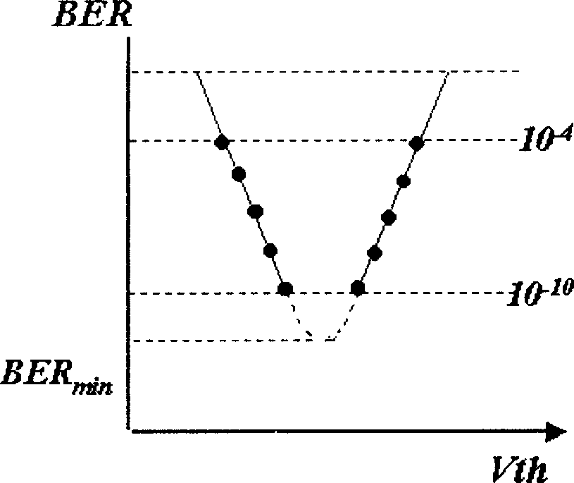
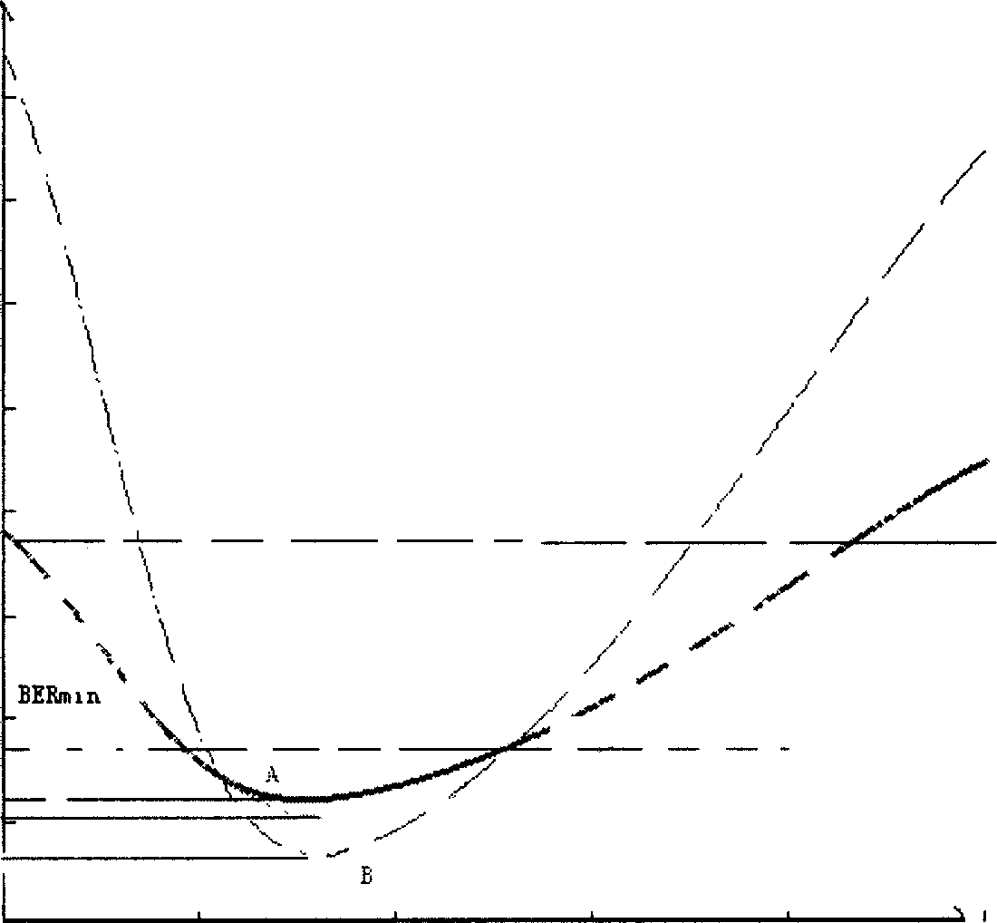
[0013] The present invention will be described in further detail below through specific embodiments and in conjunction with the accompanying drawings. The method of this patent is in figure 2 It is reflected in the fact that it is based on the fact that when the reference level is changed, the obtained bit error rate and decision level relationship curve is always U-shaped. Assuming a reference level such as figure 2 Point A in . Take the code stream recovered at this reference level (that is, the code stream recovered with this reference level as the decision level) as the reference code stream, and compare it with the code stream recovered at the changed decision level, so as to obtain the bit error rate The "U"-shaped relationship curve between BER and decision level Uth, and calculate (by fitting method) related parameters, so as to calculate the lowest bit error rate, that is, the bit error rate at the lowest point of the curve. The method of estimation can use data ...


PUM


Abstract

The method includes following steps. Code flow is recovered by using a selected reference electrical level as decision electrical level so as to obtain reference code flow. Comparing the code flow with other code flows recovered under variant decision electrical levels obtains 'U' type relation curve between first error rate and decision electrical level, and the error rate at lowest point of 'U' type relation curve is deduced. Continuing to change reference electrical level obtains multiple error rates at lowest point of 'U' type relation curve, and the lowest error rate is found out from these error rates. Value of Q factor is deduced from the lowest error rate. Since recovered data as reference code flow from reference electrical level, thus, it is not needed to prepare a standard signal as reference code flow. In this way, difficulty of monitoring on site is solved, making test more convenient.

Description

Technical field: [0001] The invention relates to a method and device for measuring the performance of an optical transmission system. Background technique: [0002] Bit Error Rate (BER) and Optical Signal-to-Noise Ratio (OSNR) are important parameters for monitoring optical fiber transmission systems. The bit error rate is not a parameter of the physical layer, and when the bit error rate is small, it takes a considerable time to measure the bit error. It is an alternative method to monitor the transmission characteristics of the system by measuring OSNR. This method is suitable for systems with large dispersion tolerance and noise-limited systems, such as 2.5Gbit / s systems. For higher rate transmission systems, OSNR can no longer describe the actual transmission performance well. A better way is to use Q factor to describe the transmission performance of the system. [0003] The key to measuring the Q factor is to find the best decision level. The bit error rate BER corr...

Claims


Application Information

Patent Timeline
IPC IPC(8): H04B10/075
Inventor 余力
Owner HUAWEI TECH CO LTD
Why Eureka
Try Eureka