Plasma display device and method for producing its front base plate

A manufacturing method and display technology, which are applied in the manufacture of discharge tubes/lamps, electrode systems, cold cathodes, etc., can solve the problems of human body damage, reduced energy utilization, and reduced brightness of plasma displays, so as to avoid harm, The effect of increasing the brightness

Inactive Publication Date: 2004-07-14
HONG FU JIN PRECISION IND (SHENZHEN) CO LTD +1
View PDF0 Cites 1 Cited by
  • Summary
  • Abstract
  • Description
  • Claims
  • Application Information

AI Technical Summary

Problems solved by technology

However, since the ultraviolet light is emitted in all directions, there will be part of the ultraviolet light 7 emitted from the upper glass substrate 1, and thus this part of the emitted ultraviolet light 7 cannot be used to bombard the fluorescent layer 9, the energy utilization rate is reduced, and the electric current is reduced. Plasma Display Brightness
At the same time, since the ultraviolet light 7 will shoot to the human body after passing through the upper glass substrate 1, it will cause damage to the human body.

Method used


Image

  • Plasma display device and method for producing its front base plate
  • Plasma display device and method for producing its front base plate
  • Plasma display device and method for producing its front base plate

Examples


Embodiment Construction

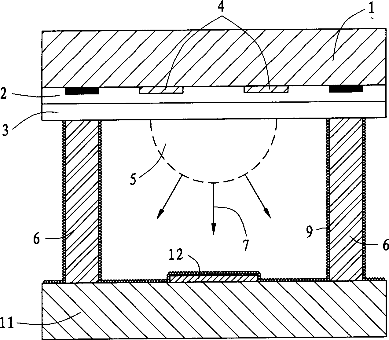
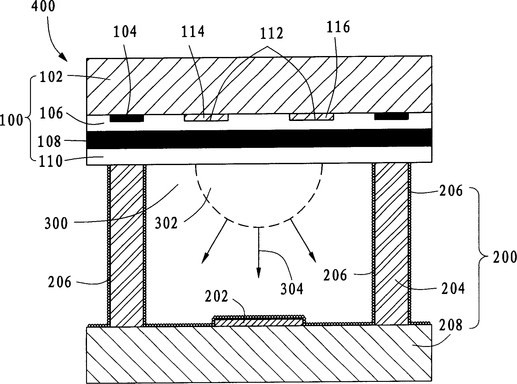
[0012] Please refer to figure 2 The plasma display 400 of the present invention includes a front substrate 100, a rear substrate 200 and a plurality of discharge grooves 300, wherein the front substrate 100 is opposite to the rear substrate 200, and the plurality of discharge grooves 300 are arranged between the front substrate 100 and the rear substrate 200. between the rear substrates 200 .

[0013] The front substrate 100 includes an upper glass substrate 102, an electrode group array 112, a black matrix 104, a dielectric layer 106 and a protective layer 110, wherein the upper glass substrate 102 is used to carry the electrode group array 112, black matrix 104 , the dielectric layer 106 and the protection layer 110 . The electrode set array 112 and the black matrix 104 are deposited on the upper glass substrate 102 , and the dielectric layer 106 and the protective layer 110 are sequentially covered on the electrode set array 112 and the black matrix 104 . Wherein, the el...


PUM


Abstract

An electric pulp display includes a front baseplate, composed of a top glass basis, an inducing layer and an electrode set array, a back baseplate composed of a bottom glass basis, an electrode array, multiple blocking walls and a fluorescent layer, multiple discharging notches placed in a preset space surrounded by the front baseplate, back baseplate and the blocking walls and full filled with inert gas excited to emit UV-light when a voltage is added to the arrays and the front baseplate includes a UV-light protection layer reflecting the UV-light emitting upward to the top glass baseplate to the back one.

Description

【Technical field】 [0001] The invention relates to a plasma display, in particular to a high-brightness plasma display and a method for manufacturing the front substrate thereof. 【Background technique】 [0002] The light-emitting principle of plasma display is similar to that of eye lamp. Inert gas or mercury gas is injected into the discharge tank made of vacuum glass tube, and then high voltage is used to make the gas produce plasma effect, and the ultraviolet light is emitted to bombard the phosphor to emit visible light. The color of visible light is determined by the type of phosphor, and the image of the plasma display is formed by the arrangement and combination of many small grids similar to eye lights. [0003] In the application field of large-size displays, compared with LCD (LiquidCrystal Display, liquid crystal display) and CRT (Cathode Ray Tube, cathode ray tube display), plasma display has the advantages of thin thickness, light weight, wide viewing angle, larg...

Claims


Application Information

Patent Timeline
Patent Type & Authority Applications(China)
IPC IPC(8): H01J9/00H01J17/02H01J17/49
Inventor 林明辉
Owner HONG FU JIN PRECISION IND (SHENZHEN) CO LTD
Why Eureka
Try Eureka