Annular space gas lifting type loop reactor

A technology of reactor and internal circulation, applied in chemical instruments and methods, chemical/physical processes, etc., can solve the problems of large initial bubble diameter, poor gas distribution effect, particle deposition clogging distributor, etc., and achieve good gas-liquid separation , Good gas-liquid separation effect

Inactive Publication Date: 2005-04-13
TSINGHUA UNIV
View PDF0 Cites 17 Cited by
  • Summary
  • Abstract
  • Description
  • Claims
  • Application Information

AI Technical Summary

Problems solved by technology

At present, most researchers increase the expansion section on the top of the reactor to reduce the liquid velocity to achieve the purpose of gas-liquid separation. However, when the operating gas velocity is high, the expansion section is simply used as the gas-liquid separator due to the excessive liquid velocity. The separation efficiency is not high, and a large number of air bubbles will be entrained into the downcomer, which cannot guarantee the required separation effect
[0005] In the gas-liquid and gas-liquid-solid loop reactors reported in the literature, orifice-type distributors are mostly used. Such gas distributors have the following problems: 1) The gas distribution effect is not good, and the initial bubble diameter of the general orifice-type distributor distribution Larger, and uneven air distribution during operation due to partial blockage of distribution holes
2) Generally, the position of the orifice distributor is at the bottom of the reactor, lower than the lower edge of the inner cylinder. When it is applied to a slurry system, it is easy to cause the problem of particle deposition to block the distributor
[0006] In a loop reactor, when the reactor operates at a higher superficial gas velocity, due to the strong coalescence of the bubbles, the size distribution of the bubbles in the riser is uneven, and a large number of large bubbles are formed, resulting in mass transfer. Decreased performance, lower conversion rate

Method used


Image

  • Annular space gas lifting type loop reactor
  • Annular space gas lifting type loop reactor
  • Annular space gas lifting type loop reactor

Examples


Embodiment approach

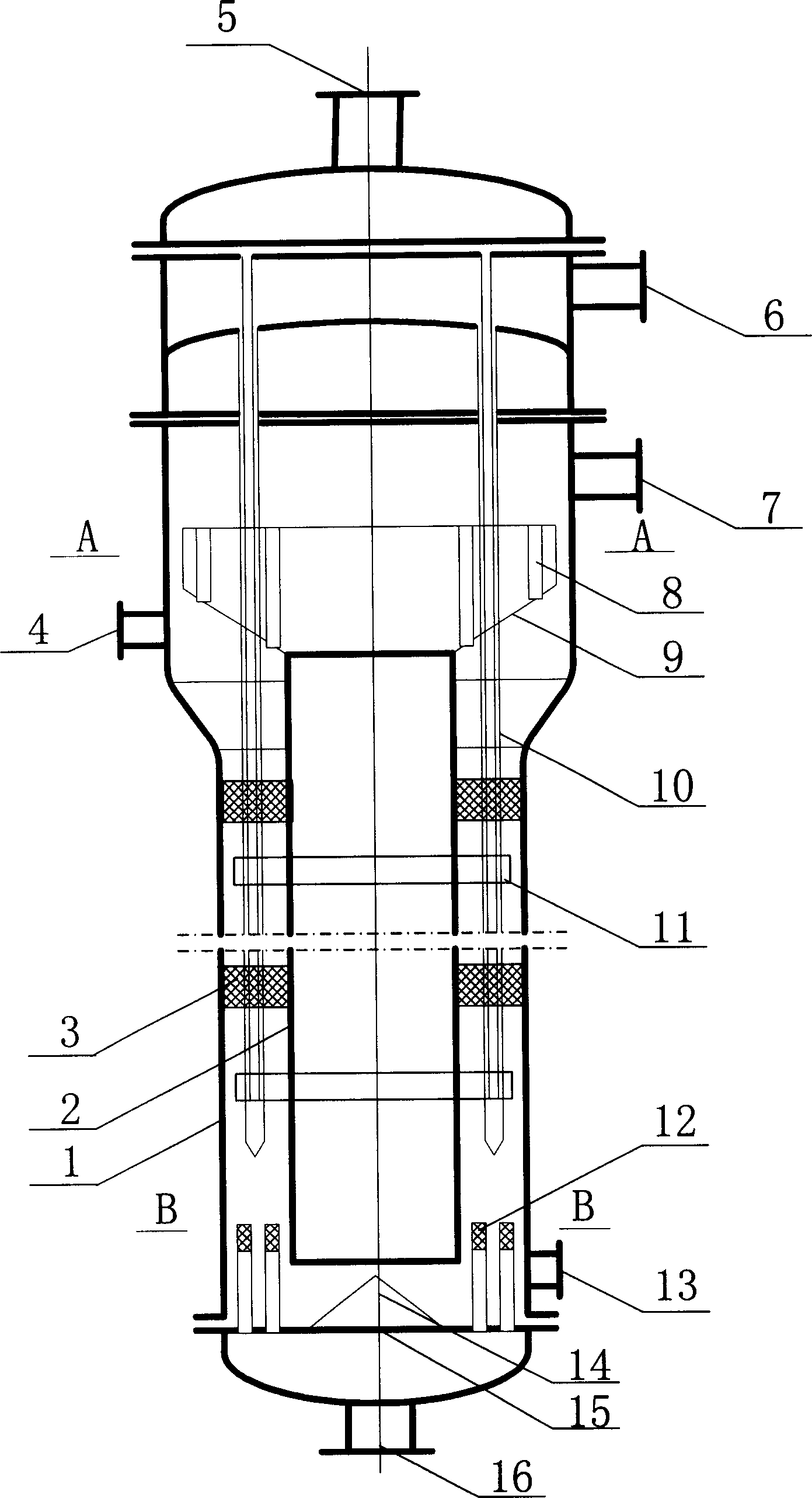
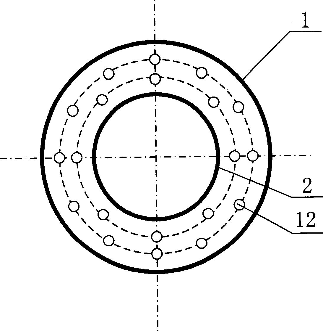
[0021] The annulus air-lift internal circulation reactor provided by the present invention is mainly composed of a reactor outer cylinder 1, a reactor inner cylinder 2 installed concentrically with the reactor outer cylinder, an internal member 3 arranged in the annulus riser, and a heat exchange reactor. Component 10, the gas-liquid separator funnel 9, the vertical thin tube 8 installed on the tapered side wall of the gas-liquid separator funnel (the gas-liquid separator funnel 9 forms together with all the vertical thin tubes 8 installed thereon gas-liquid separator), the distributor substrate 15 arranged at the bottom of the reactor and the gas distribution pipe 12 arranged on the substrate, and the conical guide plate 14 are formed, such as figure 1 shown. The bottom end of the reactor outer cylinder 1 is connected to the distributor base plate 15 in the form of a flange, and there is a certain distance between the reactor inner cylinder 2 and the distributor base plate 15...


PUM


Abstract

The annular air-lift inner circulating reactor is one inner circulating reactor with high gas-liquid separating efficiency and excellent gas distributing effect. Technologically, the present invention features that the gas-liquid separator in funnel-fine pipe separating structure has complete gas-liquid separation; and that the sintered pipe gas distributor has relatively small initial bubble size resulting in excellent gas distributing effect. In order to improve flow and reinforce mass transfer, the annular air-lift pipe is provided with inner member; and in order to introduce out or in heat for reaction, the annular air-lift pipe is provided with heat exchange member of fingered or coiled pipe. The reactor has the features of high gas-liquid separating efficiency, high gas distributing effect, homogeneous radial gas distribution, homogeneous radial liquid speed distribution and no reverse fluid circulation.

Description

technical field [0001] The invention relates to a reactor suitable for gas-liquid and gas-liquid-solid multiphase flow reaction systems, in particular to an annulus air-lift internal circulation reactor, which belongs to the technical field of chemical equipment. Background technique [0002] Loop reactors are widely used in many fields such as chemical industry, energy, environment, and biochemistry. Compared with stirred tanks, airlift loop reactors have a simpler structure. Circulating flow in the bed. Loop reactors are divided into two types: inner loop and outer loop. Compared with the outer loop reactor, the inner loop reactor has the advantages of simple structure and easy processing. In the outer loop reactor, both ends of the downcomer are connected to the riser by flanges. Since the actual reaction system is mostly a high-temperature and high-pressure system, high requirements are placed on the thermal expansion matching and pressure resistance of the material, w...

Claims


Application Information

Patent Timeline
Patent Type & Authority Applications(China)
IPC IPC(8): B01J8/00
Inventor 王金福张同旺王铁峰王德峥金涌
Owner TSINGHUA UNIV
Why Eureka
Try Eureka