Pneumatic tire and tire mold

A technology for pneumatic tires and tire molds, which is applied to tire treads/tread patterns, tire parts, tires, etc., and can solve problems such as inability to effectively suppress defects or cracks

Inactive Publication Date: 2005-07-13
YOKOHAMA RUBBER CO LTD
View PDF1 Cites 5 Cited by
  • Summary
  • Abstract
  • Description
  • Claims
  • Application Information

AI Technical Summary

Problems solved by technology

[0004] However, if a split type tire mold is simply used, depending on the rubber material used for

Method used


Image

  • Pneumatic tire and tire mold
  • Pneumatic tire and tire mold
  • Pneumatic tire and tire mold

Examples


specific Embodiment

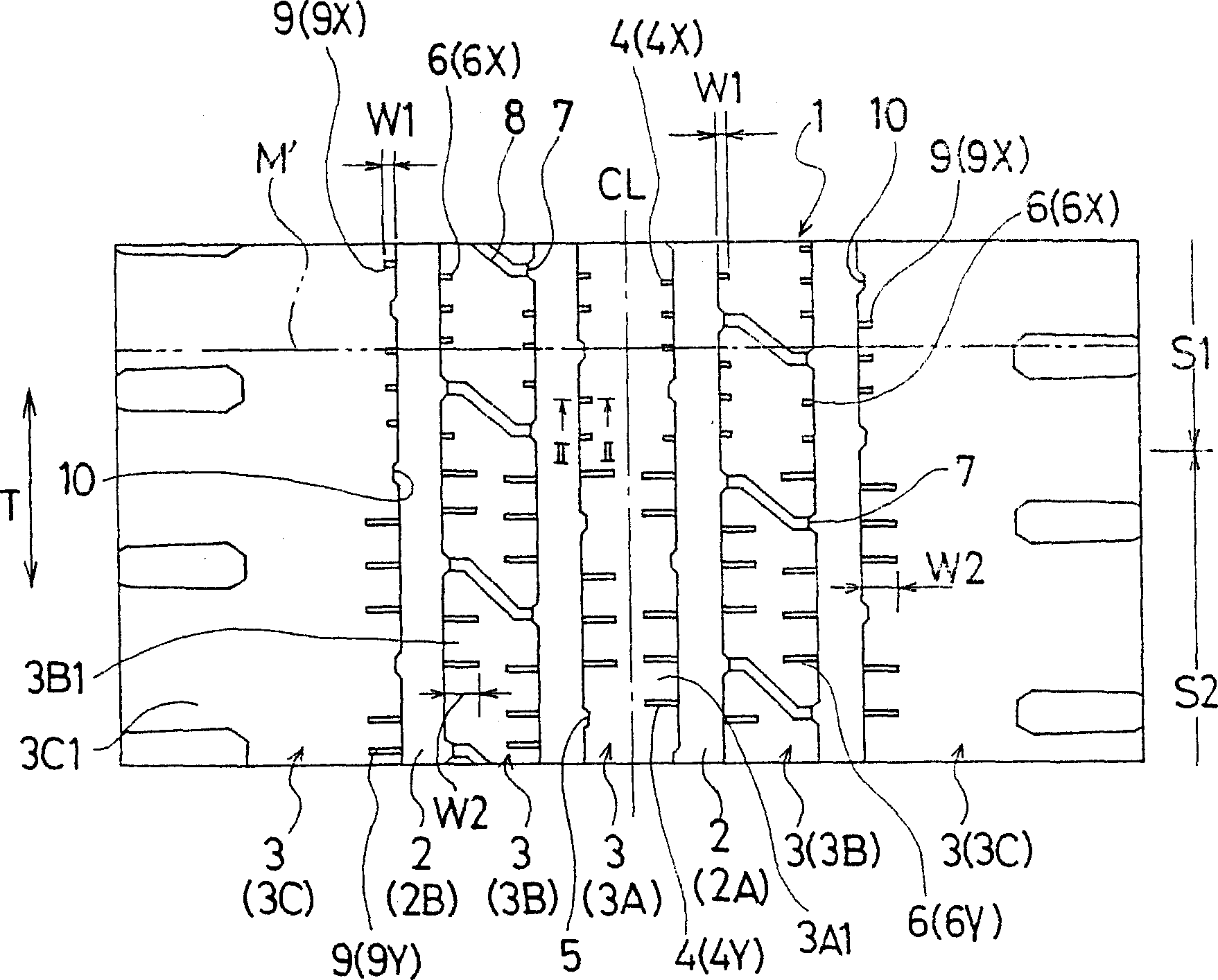
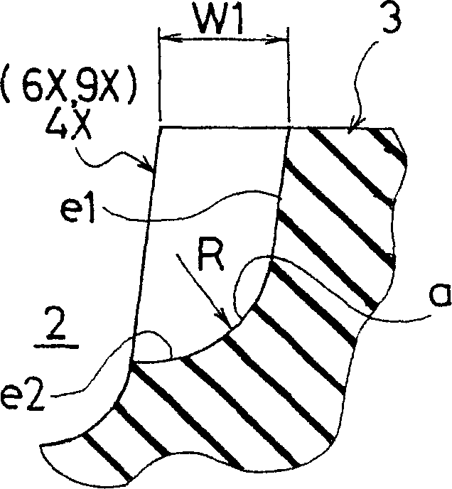
[0076] Assuming the same tire size as 145R12 6PR LT, the length in the tire width direction of the first sipe located in the first region S1 is shorter than that of the second sipe located in the second region S2 figure 1 In the tire 1 of the present invention having the structure shown, the opening end of the sipe located on the far side of the tread position M' where the distance of the first sipe coincides with the division position M of the sector is rounded. The shape of the edge of the first fine line on the far side of the tread position M' where the distance of the first fine line coincides with the division position M of the sector is rounded, Image 6 Ten tires of the present invention tire 2 having the structure shown and the conventional tires of the present invention tire 1 in which the tire width direction length of the fine lines were the same were taken, and vulcanized and molded using a split type tire mold.

[0077] In each of the test tires, a rubber having ...


PUM


Abstract

The present invention is a pneumatic tire vulcanized and molded by a split type tire mold composed of a plurality of sectors formed by dividing an annular side mold having a tread forming surface for forming a tread in the circumferential direction. . On the tread having the first region formed by the region near the sector division position of the sideform and the second region formed by the region far from the sector division position of the sideform, there is at least one tire extending in the circumferential direction of the tire. The land portion formed by dividing the circumferential grooves. In at least one of the land portions, fine lines extending from at least one of the circumferential grooves and extending from at least one of the land portions are arranged at predetermined intervals in the tire circumferential direction. The fine lines include first fine lines located in the first region and second fine lines located in the second region. The length W1 in the tire width direction of the first sipe is shorter than the length W2 in the tire width direction of the second sipe.

Description

technical field [0001] The present invention relates to a pneumatic tire and a split (combined) type tire mold used for vulcanization molding thereof, and more specifically, relates to a method for suppressing occurrence of chipping (peeling) or cracks in a land portion (land portion) of a tread Pneumatic tires and tire moulds. Background technique [0002] Conventionally, for example, there is a pneumatic tire in which a land portion composed of reinforcing ribs is defined on the tread surface by circumferential grooves extending in the tire circumferential direction, and only one end is arranged on the land portion at predetermined intervals in the tire circumferential direction. A sip that opens in a circumferential groove and extends in the tire width direction (for example, refer to Japanese Patent Application Laid-Open No. 5-178018). [0003] Such a pneumatic tire with fine lines on the ribs is usually vulcanized and molded using a split tire mold instead of a half-di...

Claims


Application Information

Patent Timeline
IPC IPC(8): B29C33/02B29C33/42B29C35/02B29D30/06B29D30/52B29L30/00B60C11/00B60C11/01B60C11/12
CPCB29D30/0606B29D2030/0613B60C11/01B60C11/0318B60C11/12B60C11/1263Y10S152/03
Inventor 松村智之
Owner YOKOHAMA RUBBER CO LTD
Why Eureka
Try Eureka