Single-lip drill

A single-edged drill bit and drill bit technology, which is applied in the direction of drill repair, drilling tool accessories, drilling/drilling equipment, etc., can solve the problems of not being able to maintain the original function for a long time, insufficient blade tip strength, and loss of adhesion. Achieves the effect of suppressing chipping or breakage of the chisel edge, preventing unstable adhesion, and stabilizing adhesion

Inactive Publication Date: 2009-12-02
SUMITOMO ELECTRIC HARDMETAL CORP
View PDF5 Cites 2 Cited by
  • Summary
  • Abstract
  • Description
  • Claims
  • Application Information

AI Technical Summary

Problems solved by technology

[0005] However, since the tip of the drill in Patent Document 1 is formed of dots, the strength of the cutting edge will be insufficient, so chipping and damage of the chisel edge are likely to occur at the initial stage of drilling.
Therefore, the good adhesion is lost at an early stage and the original function cannot be maintained for a long time
Moreover, in the manufacturing process of the drill bit, it is very difficult to process the chisel edge at one point in the rotation center, and it is difficult to avoid quality deviation

Method used


Image

  • Single-lip drill
  • Single-lip drill
  • Single-lip drill

Examples


Embodiment Construction

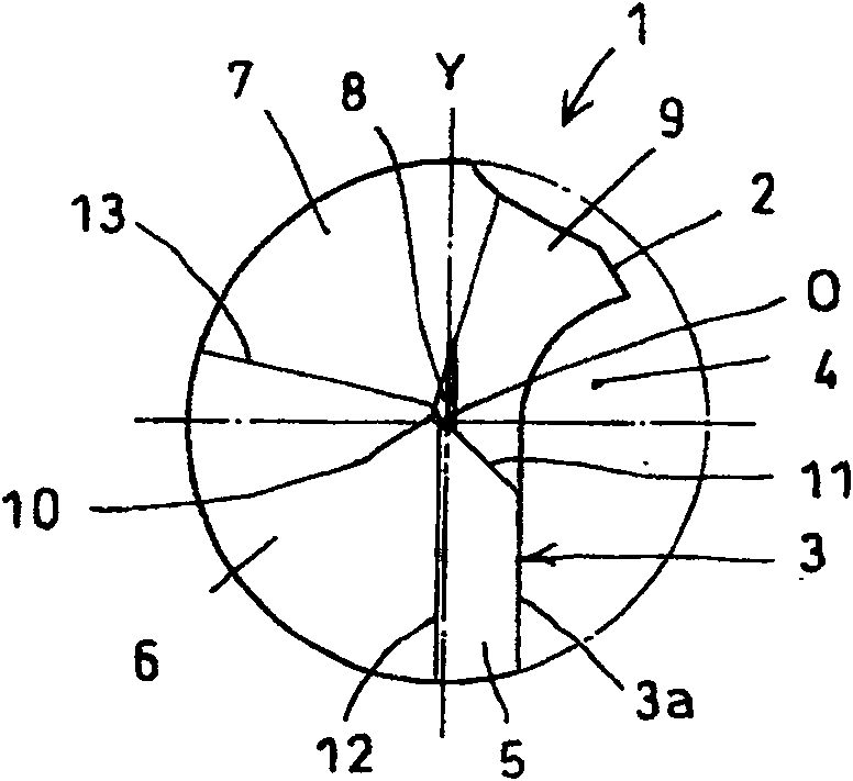
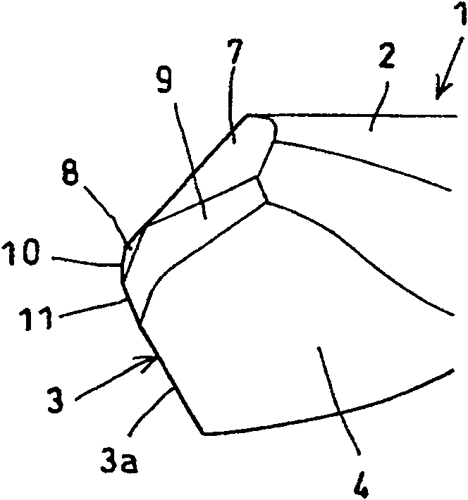
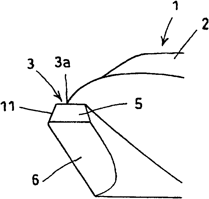
[0034] The following is based on the attached Figure 1-7 Embodiments of the present invention will be described. Figure 1 to Figure 6 A single-edged drill according to the first embodiment is shown. Each figure is enlarged for easy understanding. The drill 1 has a main body 2 integrally formed with a shank (not shown), a cutting edge 3 is formed at the front end of the main body 2, and a chip discharge groove 4 is formed on the main body. The chip discharge groove 4 is preferably a spiral groove as shown in the figure. The main cutting edge portion 3 a of the cutting edge 3 is located just past the center (in front of a line Y passing through the axis O in the drill rotation direction). In addition, the rotation direction of the drill bit in the present invention refers to the forward rotation direction of the drill bit.

[0035] In addition, in this drill 1, the relief portion at the front end is formed by a plurality of stages of relief surfaces. In the first embodime...


PUM


Abstract

This invention is to provide a drill with a single cutting edge capable of stabilizing engagement with the work piece, preventing fractures of a chisel point to maintain high bore position accuracy over a long time, and causing less scatter of quality in manufacturing. The structure of this drill with a single cutting edge 3 and one chip flute 4 comprises multiple connected relief faces of the relief portion at the front end of the drill. At the foremost end of the drill is a first chisel edge, which is formed by the intersection of two relief faces and is perpendicular to the axial center and positioned at a rotary center of the drill. The first chisel edge is connected to the second chisel edge, which is formed by the intersection of two relief faces. The outer end of the second chisel edge is connected to the main cutting edge, where the opposite end of the second chisel edge is connected to the other end of the first chisel edge.

Description

technical field [0001] The present invention relates to a small-diameter single-edged drill for drilling holes in printed substrates and the like. Background technique [0002] For example, the diameter of drills used for processing printed substrates tends to decrease day by day. If the small-diameter drill adopts a single-edge structure, it can suppress the decrease in rigidity due to the reduction of the cross-sectional area, and reduce breakage and deviation during machining. However, the attachment of the drill bit with a single-edged structure to the workpiece is unstable, the main body is easy to vibrate during processing, and the hole position accuracy is poor. [0003] For this reason, the following Patent Document 1 discloses a single-edged drill in which the tip (chisel edge portion) protruding toward the drill tip side in the tip relief surface is composed of one point, and the change in the axis of the drill tip protrudes from it. The amount of position (eccen...

Claims


Application Information

Patent Timeline
Patent Type & Authority Patents(China)
IPC IPC(8): B23B51/00
CPCG06K19/07749
Inventor 福田辰郎藤泽伸也江口敏郎今村诚山口直树
Owner SUMITOMO ELECTRIC HARDMETAL CORP
Why Eureka
Try Eureka