Cutting insert and cutting tool and cutting method employing it

A technology for cutting inserts and cutting tools, which is applied in the direction of milling cutting blades, manufacturing tools, accessories of tool holders, etc. It can solve the problems of cutting edge defects and cracks easily, and achieve the effect of suppressing defects and superior machining accuracy

Active Publication Date: 2010-03-24
KYOCERA CORP
View PDF1 Cites 2 Cited by
  • Summary
  • Abstract
  • Description
  • Claims
  • Application Information

AI Technical Summary

Problems solved by technology

Therefore, stress concentrates at the connection point between the transition region B and the flank region C connected to the lower side of the trans

Method used


Image

  • Cutting insert and cutting tool and cutting method employing it
  • Cutting insert and cutting tool and cutting method employing it
  • Cutting insert and cutting tool and cutting method employing it

Examples


Example Embodiment

[0022]

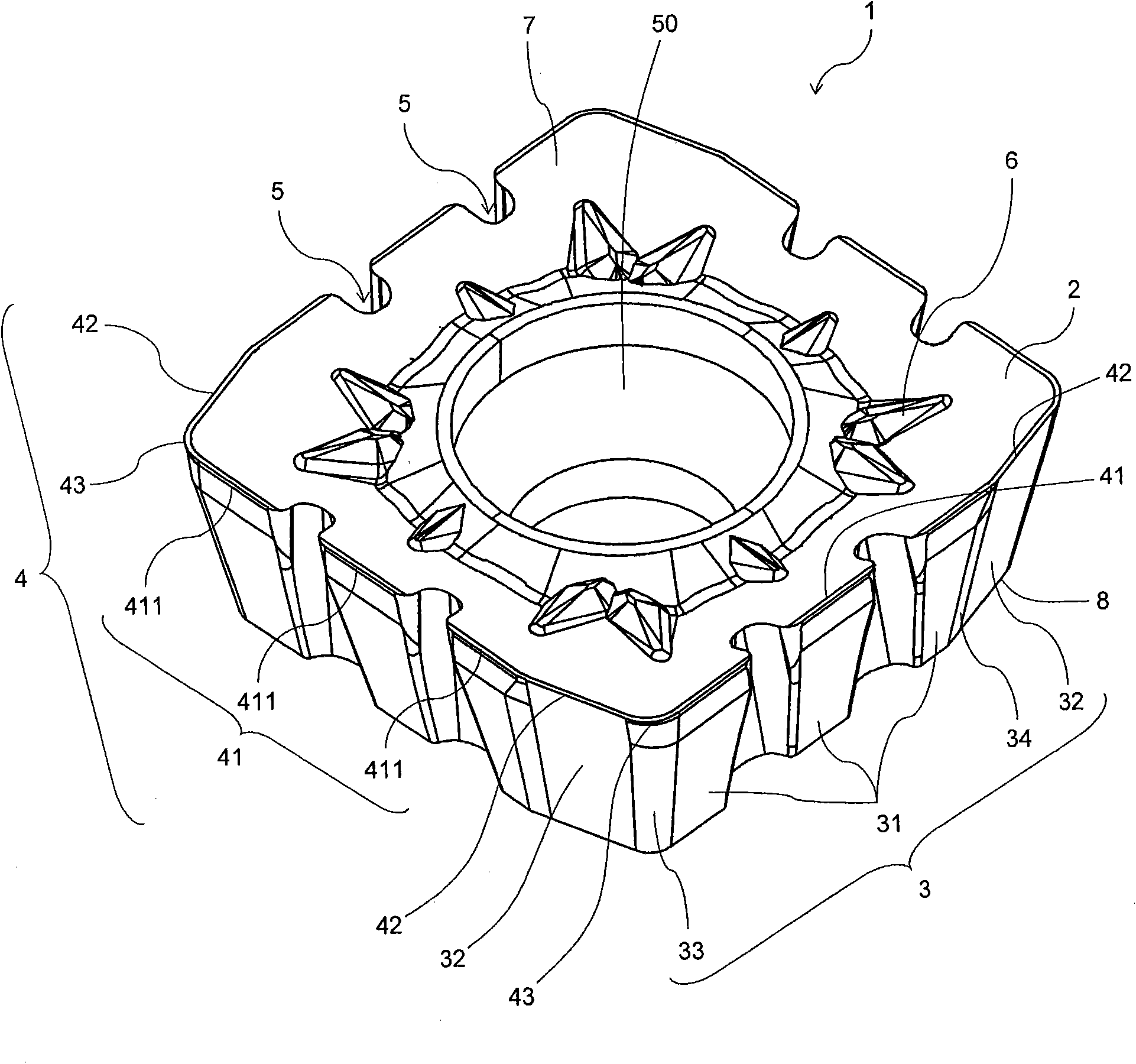
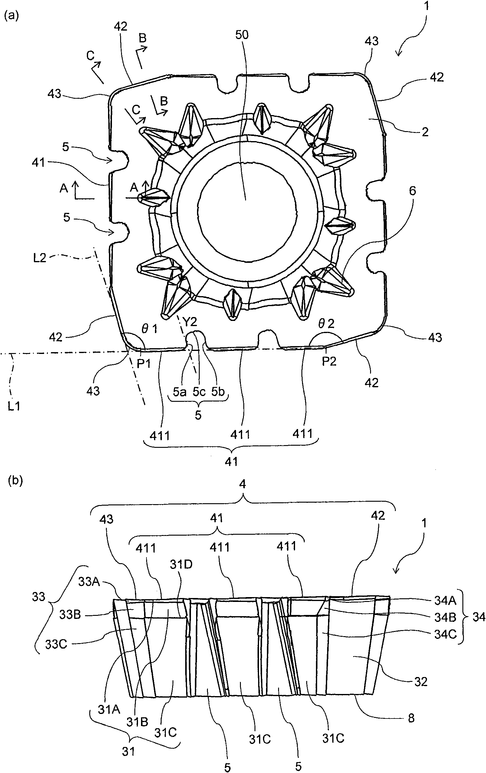
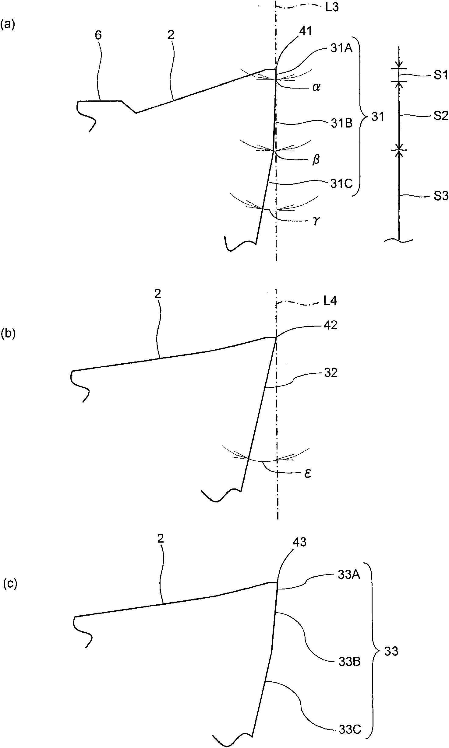
[0023] Below, refer to Figure 1 ~ Figure 4 An embodiment of the cutting insert of the present invention (hereinafter referred to as an insert) will be described in detail. Such as figure 1 As shown, the insert 1 of this embodiment has a body portion 7, wherein the body portion 7 has: a substantially polygonal upper surface; a lower surface 8; and a side surface. The main body 7 has a rake surface 2 formed on at least a part of the upper surface; a flank surface 3 formed on at least a part of the side surface; and a cutting edge 4 formed at the intersection of the rake surface 2 and the flank surface 3.

[0024] The cutting edge 4 has: a first cutting edge 41; a second cutting edge 42; and a third cutting edge 43. The third cutting edge 43 is located between the first cutting edge 41 and the second cutting edge 42 and is located at a substantially polygonal corner in a plan view. The first cutting edge 41 functions as a main cutting edge. The second cutting edge 42 f...


PUM


Abstract

A cutting insert having a substantially polygonal upper surface, a lower surface, a side face with a flank, and a cutting edge formed at the intersection of the upper surface and the side face.The cutting edge has a first cutting edge, a second cutting edge, and a third cutting edge located between the first and second cutting edge at the corner of the polygon. The flank has a first flank corresponding to the first cutting edge, and a second flank corresponding to the second cutting edge. The first flank has an upper flank connected with the first cutting edge, a middle flank located on the lower surface side of the upper flank, and a lower flank located on the lower surface side of the middle flank.Assuming the clearance angle of the upper flank is alpha, the clearance angle of the middleflank is belta, the clearance angle of the lower flank is gamma, and the clearance angle of the second flank is epsilon, the alpha, belta, gamma and epsilon satisfy the relation alpha<belta<gamma<epsilon. The cutting insert is attached to a cutting tool, and a cutting method employs the cutting tool.

Description

technical field [0001] The present invention relates to a cutting insert for a cutting tool, a cutting tool equipped with the cutting insert, and a cutting method using the cutting tool. Background technique [0002] Conventionally, cutting tools such as face mills and end mills, especially throw away cutting tools which are economical and use a cutting insert mounted in a holder, have been frequently used. [0003] For example, Patent Document 1 discloses a cutting insert having a major cutting edge (first cutting edge) located on one corner portion and a minor cutting edge (second cutting edge) located on the other. In this cutting insert, the relief surface corresponding to the first cutting edge is different from the relief surface corresponding to the second cutting edge. [0004] Specifically, in the cutting insert described in Patent Document 1, the flank surface corresponding to the first cutting edge is composed of a plurality of divided regions. The relief angle ...

Claims


Application Information

Patent Timeline
IPC IPC(8): B23B27/14B23B27/00B23C5/06
CPCB23C5/202B23C2200/128B23C2210/0407B23C5/06B23C2200/205B23C2200/125Y10T407/23Y10T407/1924
Inventor 石田琢也
Owner KYOCERA CORP
Why Eureka
Try Eureka