

Aroma diffuser
A kind of aroma device and container technology, which is applied in the direction of vaporizing substances, disinfection, etc.
- Summary
- Abstract
- Description
- Claims
- Application Information
AI Technical Summary
Problems solved by technology
Method used
Image

Examples
Embodiment 1
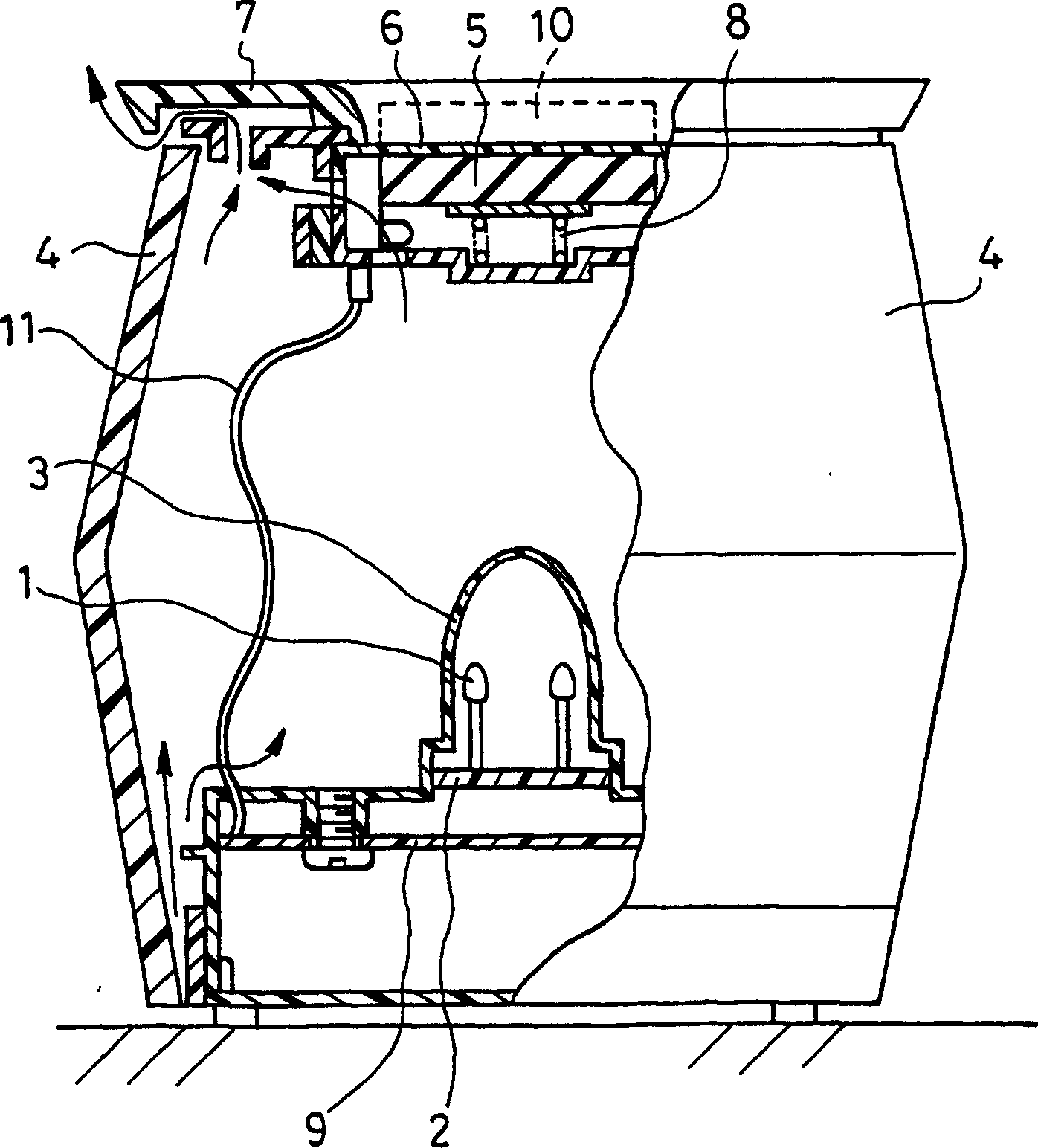
[0039] figure 1 It is a longitudinal sectional view showing the structure of the aroma device of Example 1.
[0040] In the figure, 1 is an LED as a light source. Place 4 LEDs at 90° intervals (at figure 1 , assuming that the center line of the aroma device (not shown) is used as the polar coordinate system of the axis, and the polar coordinates are used to express the mutual angle of the intersection point (4 points) of the plane perpendicular to the center line (for the paper) and LED1) when installing on the LED substrate 2. 3 is the 1st cover which covers LED1 and diffuses and transmits light. Reference numeral 4 denotes a second cover provided outside the first cover 3 to diffuse and transmit light at least part or all of the side surfaces, and has openings on both sides in the vertical direction. exist figure 1 In the drawing, the cross-sectional shapes of the first cover 3 and the second cover 4 taken on a plane perpendicular to the paper surface are approximately ...
Embodiment 2
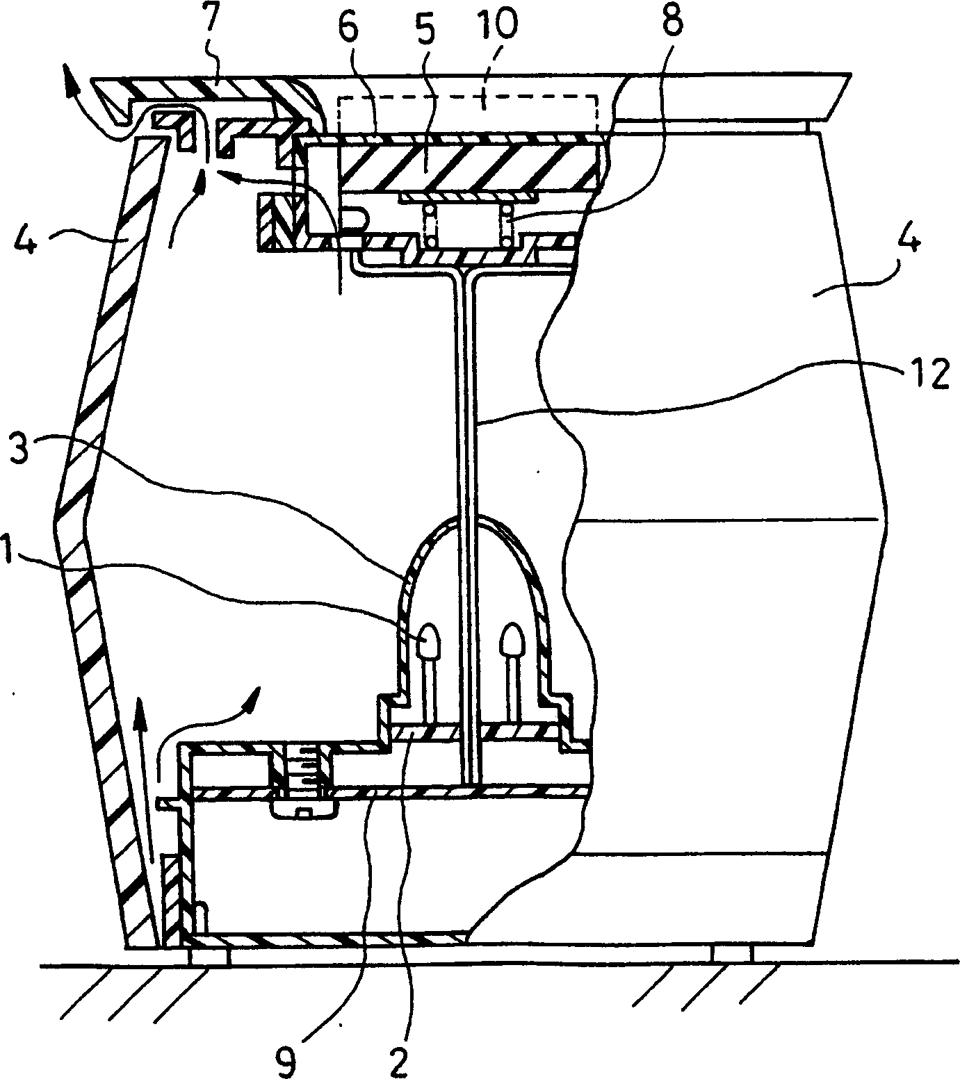
[0053] figure 2 It is the aroma device which shows Example 2. Since the basic configuration is the same as that of Embodiment 1, the same symbols are attached to the same parts, and descriptions thereof are omitted, and the differences are mainly described.
[0054] In this example, three LEDs 1 are provided on the LED substrate 2 at intervals of 120° (mutual angles when represented by the same polar coordinates as in Example 1). In addition, holes of Φ4 mm each are provided in the upper part of the first cover 3 and the LED substrate 2 through which the light of the LED 1 is diffused and transmitted, and the heater wiring 12 passes therethrough. The heater wiring 12 is configured to stand upright from the centers of the LEDs 1 . The heater 5 is arranged above the LED 1 and connected to the heater wiring 12 .
[0055] The operation of the above-mentioned aroma device is the same as that of Embodiment 1, but by making the heater wiring 12 stand upright from the center of ea...
Embodiment 3
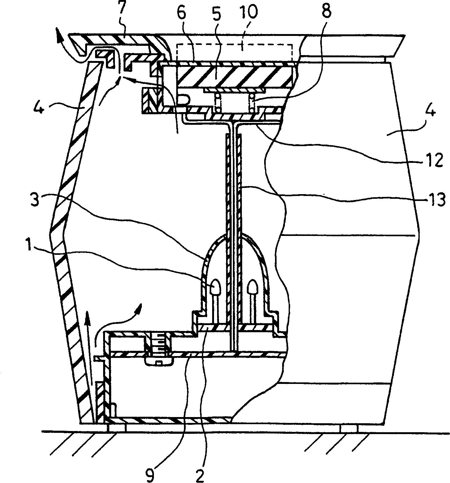
[0059] image 3 It is the aroma device which shows Example 3. The basic configuration is the same as that of Embodiment 2, so the same symbols are attached to the same parts, and descriptions are omitted, and the differences are mainly described.
[0060] Heater wires 12 standing upright from the centers of the LEDs 1 are bundled together with holding tubes 13 . In addition, the heater 5 uses a PTC heater.
[0061] In the above-mentioned aroma device, by bundling the heater wires 12 in the holding pipe 13, the heater wires 12 can be integrated and stand more vertically without the shadow of the heater wires 12 being seen.
[0062] In addition, the color tone of the holding pipe 13 is made to be the same color as the luminous color of the LED 1 and lighter, so that the shadow of the heater wiring 12 can no longer be seen.
[0063] By using a PTC heater as the heater 5, the temperature of the heater 5 can be prevented from reaching a temperature higher than the Curie temperat...
PUM
 Abstract
Description
Claims
Application Information