Terminal device of switching device

A terminal device and switch technology, applied in the direction of switch terminal/connection, protective switch terminal/connection, electric switch, etc., can solve the problem of inability to ensure space, and achieve the effect of ensuring finger protection function and improving safety.

Inactive Publication Date: 2005-08-31
FUJI ELECTRIC FA COMPONENTS & SYST CO LTD
View PDF1 Cites 16 Cited by
  • Summary
  • Abstract
  • Description
  • Claims
  • Application Information

AI Technical Summary

Problems solved by technology

In addition, if a connection module, an electromagnetic contactor, etc. are arranged adjacent to the switch, a sufficient space cannot be ensured between them, and there is also a problem that it is difficult to manually lift up the terminal lifter at the handle portion.

Method used


Image

  • Terminal device of switching device
  • Terminal device of switching device
  • Terminal device of switching device

Examples


Embodiment Construction

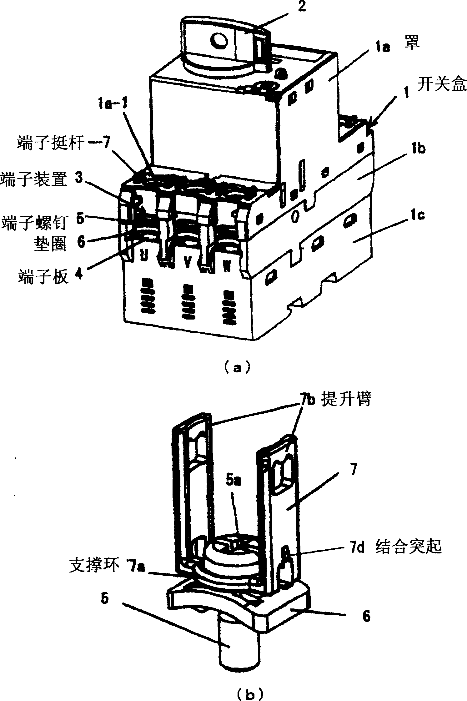
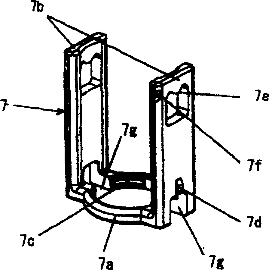
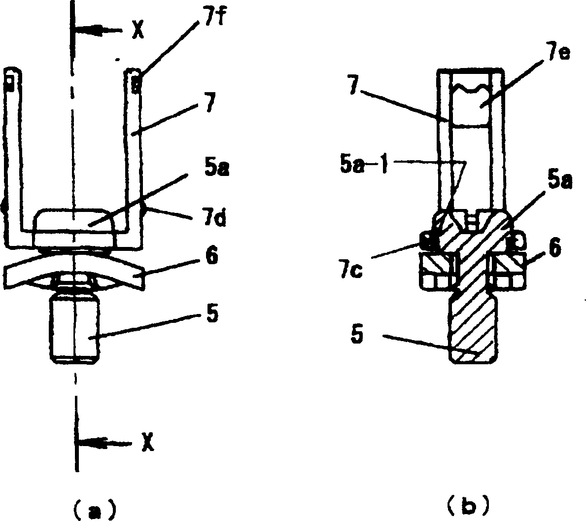
[0052] The following is based on Figure 1 to Figure 9 The illustrated examples illustrate implementation of the invention. First, in figure 1 (a) and (b) respectively show the general view equipped with the switch (connection breaker for three-phase circuit) of the present invention, and the states where washers and terminal tappets are joined to terminal screws.

[0053] exist figure 1 Among them, 1 is a switch composed of a three-part structure of cover 1a, middle box 1b, and lower box 1c; 2 is a handle for switch operation installed on the upper surface of the cover; On the terminal boards on the load side and the load side, the terminal device 3 of the present invention is formed here. Here, the terminal device 3 is the terminal board 4 of the main circuit corresponding to each phase of U, V, and W, which is drawn from the current interrupting part inside the box to the terminal board and arranged on the left and right. The terminal screw 5 screwed into the screw hole...


PUM


Abstract

In a terminal device of a switching device, a terminal screw with a washer is screwed in a terminal strip having a screw hole therein for connecting an external wire. The terminal strips are placed on terminal boards of power supply side and load side formed at both ends of a switching device case. A case cover covers the terminal screw, and a screwdriver is inserted through an insertion hole formed in an upper surface of the case cover to tighten the terminal screw. The terminal device includes a terminal lifter connected to the terminal screw for manually lifting the terminal screw upwardly from the upper surface of the case cover, so that the terminal screw is temporally attached to the case cover at a lifted position after the terminal screw is loosened and detached from the terminal strip with the screwdriver.

Description

technical field [0001] The present invention relates to a terminal device suitable for wiring circuit breakers, electromagnetic contactors, etc., and connecting external wiring switches to the main circuit terminals. Background technique [0002] In the above-mentioned switch, as a terminal device, a terminal combined with a washer is screwed on the terminal plate (terminal plate with screw holes) drawn from the power supply side and the load side terminal plate formed at both ends of the switch box. Screws, and use the terminal screws to fix and connect various crimp terminals (round, U-shaped crimp terminals) of wires inserted into the terminal board from the outside to the terminal board. In addition, in order to prevent electric shock accidents caused by the exposure of the charging part, the terminal device generally has a structure such that the upper surface of the terminal plate with the terminal plate and terminal screws is covered with the switch case cover of the ...

Claims


Application Information

Patent Timeline
Patent Type & Authority Applications(China)
IPC IPC(8): H01R4/38H01H1/58H01H9/02H01H50/02H01H50/14H01H71/08H01H73/20H01R4/30H01R4/34H01R9/00
CPCH01R4/34H01R4/305H01H71/08H01H9/0264H01H1/5855
Inventor 川田久夫久保山胜典武内志乃夫
Owner FUJI ELECTRIC FA COMPONENTS & SYST CO LTD
Why Eureka
Try Eureka