Endoscope

A technology for endoscopes and bending parts, applied in the field of endoscopes, can solve the problems of changing flexibility, increasing costs, and not having, and achieve the effect of suppressing bending

Active Publication Date: 2009-04-08
OLYMPUS CORP
View PDF5 Cites 0 Cited by
  • Summary
  • Abstract
  • Description
  • Claims
  • Application Information

AI Technical Summary

Problems solved by technology

In addition, an endoscope has also been conceived in which the flexibility of the protective coil can be changed by filling a part of the protective coil with a filler, but in this case, since the sparsely wound portion of the filler is not filled exposed, therefore, does not have the effect of preventing the snagging of the elevation difference
[0008] In addition, Japanese Patent Publication No. 2002-306404 and Japanese Patent Publication No. 2000-214337 may be combined to fill the sparsely wound part of Japanese Patent Publication No. 2002-306404 with a filler, but in this case, There is the following double trouble: not only to make a protection coil with a mixture of tightly wound and sparsely wound, but also, it must be filled with filler
[0009] In addition, the position of the built-in to be protected is determined by the arrangement of the built-in, the structure of the curved part, the bending angle, etc., so the position is different according to the model, and the sparse winding and Tightly wound mixed coils at higher cost
In addition, although the flexibility in the axial direction can be adjusted by providing the closely wound part, there is also a disadvantage that the flexibility cannot be changed corresponding to the circumferential direction.

Method used


Image

  • Endoscope
  • Endoscope
  • Endoscope

Examples


Embodiment 1

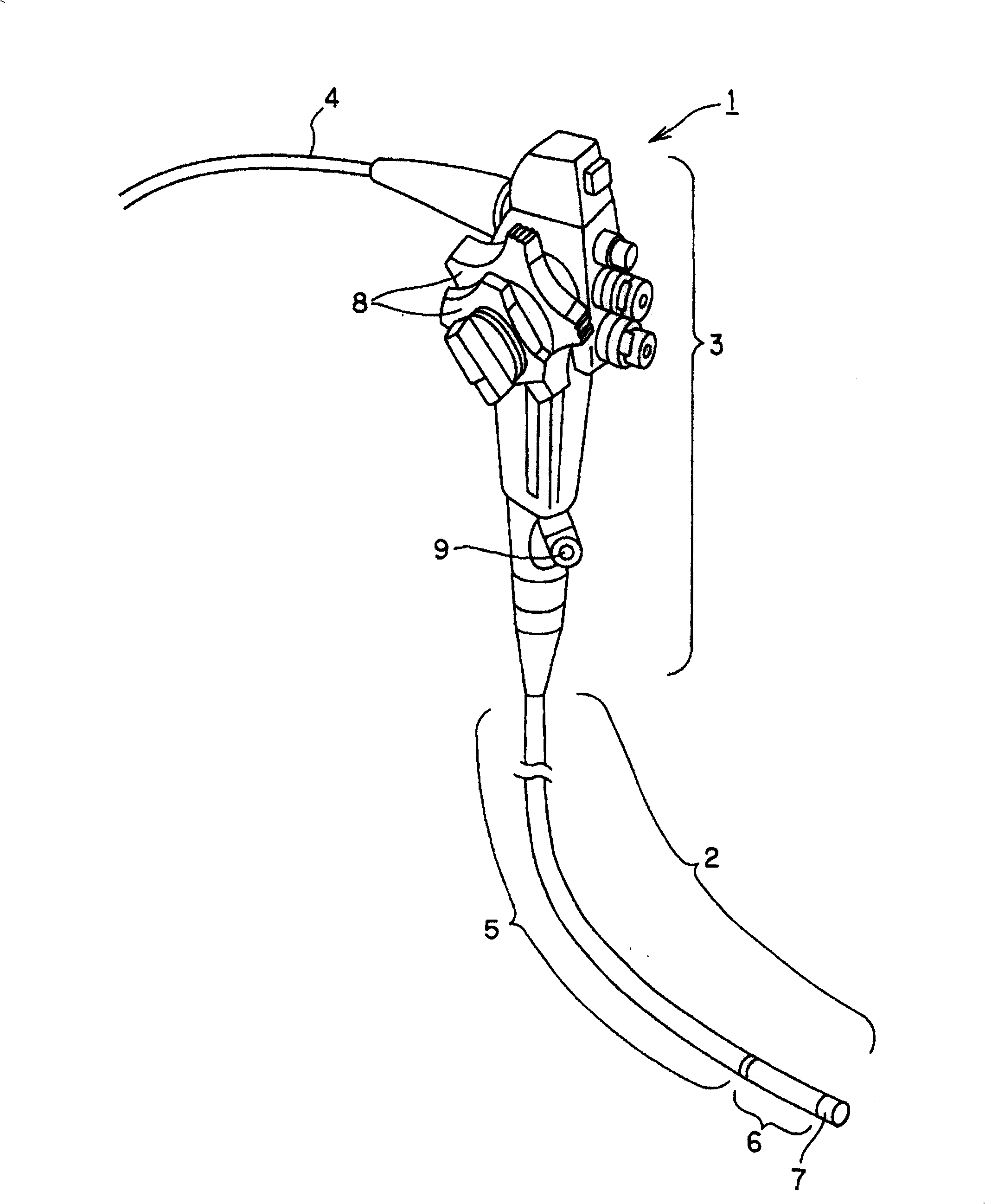
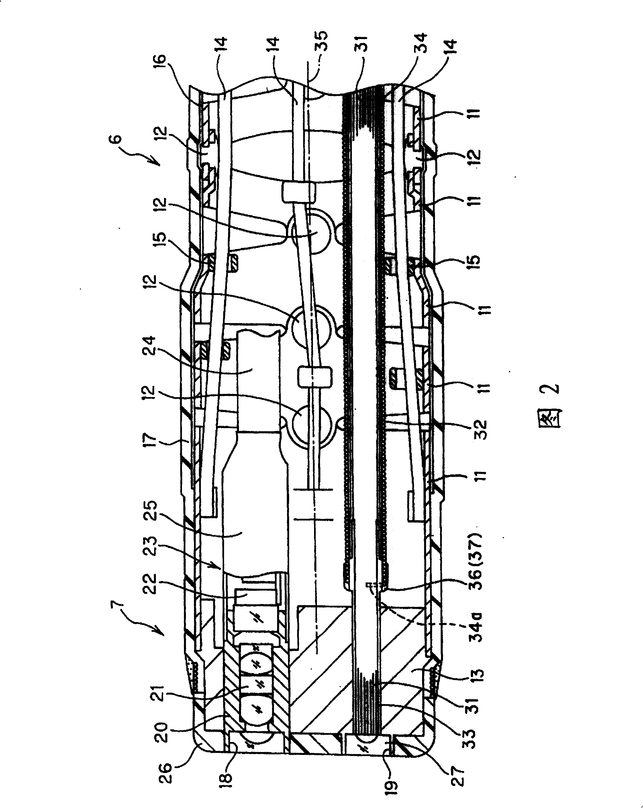
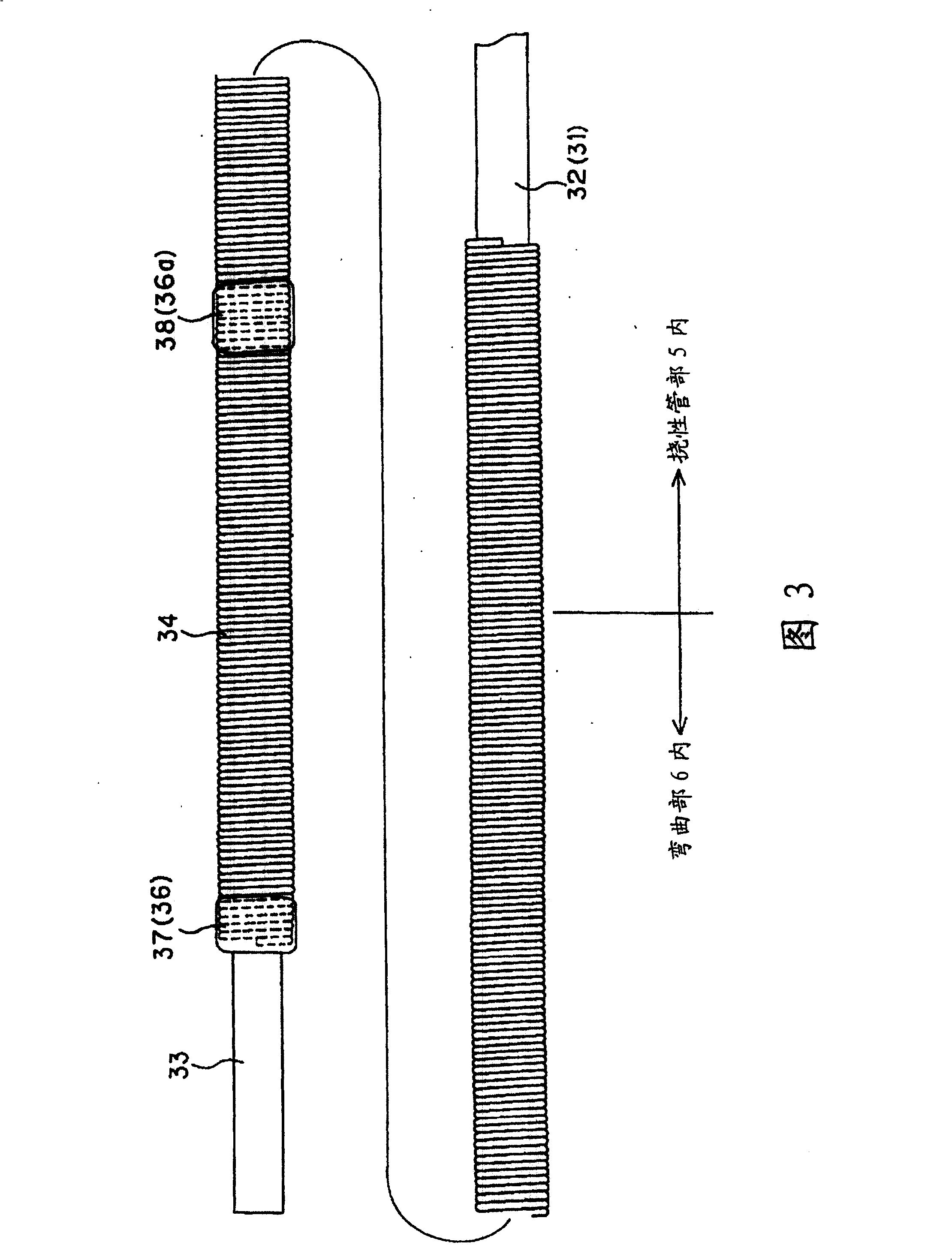
[0040] Figure 1 to Figure 13 Representing Embodiment 1 of the present invention, figure 1 The appearance of the endoscope according to Embodiment 1 of the present invention is shown. FIG. 2 shows the internal structure of the distal end side of the insertion part. FIG. 3 shows the structure in which the optical fiber bundle is protected by a protective coil member. FIG. The position of the adhesive fixed between the wires of the protective coil component is located near the center of the bent portion in the longitudinal direction, Figure 5 Indicates that the adhesive is fixed at a position where the radius of curvature is the smallest in a state where the curved portion is bent the most.

[0041] Fig. 6 and Fig. 7 show the example of the fixing position different from the fixing position of the adhesive shown in Fig. 3, Figure 8 to Figure 10 Shows the structure of the fixing portion in the circumferential direction when fixing the wires of the protective coil component, ...

Embodiment 2

[0097] Next, Embodiment 2 of the present invention will be described with reference to FIGS. 14 and 15 . This embodiment is basically the same as the embodiment 1 except that two bending parts are provided.

[0098] FIG. 14 schematically shows the bending member 11 constituting two independent first bending parts 51 and second bending parts 52 that can be bent.

[0099] FIG. 15 shows, as an example, a state where the first bending portion 51 is bent 90° toward the DOWN side, and the second bending portion 52 is bent 90° toward the UP side. Even if the bending value is the same at 90°, the total of the bending gaps 54 on the side of the second bending part 52 formed between adjacent bending parts 11 is designed to be equal to the total of the bending gaps 53 on the side of the first bending part 51. The amount (surplus) is small. In FIG. 15 , portions of the bending member 11 forming the bending gaps 53 , 54 are shown.

[0100] Although not shown in this embodiment, the prox...

Embodiment 3

[0107] Next, Embodiment 3 of the present invention will be described. First, its background will be explained. In Japanese Utility Model Publication No. 54-90086, an endoscope insertion aid of such a sliding tube type is disclosed. An insertion portion of a mirror and the like are inserted and penetrated therethrough, the slide tube assists insertion into a body cavity, etc., and an inflatable and contractible balloon is provided on the outer periphery of the tip portion of the slide tube.

[0108] In this sliding tube type endoscope insertion aid, in order to improve the sliding properties, it is necessary to increase the gap between the endoscope and the sliding tube. As a result, the diameter of the sliding tube cannot be avoided.

[0109] When the sliding tube is thicker, the radius of curvature of the tube itself becomes larger, which not only makes it difficult to bend at a small bending part in the body cavity, but also becomes less slidable with the intestinal tube du...


PUM


Abstract

The invention provides an endoscope provided with a built-in element protection means capable of protecting a built-in element and locally regulating a bend to protect it easily as well. A light guide fiber bundle 31 as a thin and long flexible built-in element is inserted in the state of being covered with an exterior tube 32 inside a curved part 6 and inside a flexible tube part 5 on the distal end side in an insertion part, and the outer side is covered with a coil member 34 for protection. Since large external force acts on the light guide fiber bundle 31 arranged at a part where the curved part 6 is largely curved, a hard part 38 is formed by adhering the adjacent strands with each other with an adhesive material 36a at the coil member 34 for the protection covering the part, the bend more than needed is regulated, and the built-in element is protected effectively over a long period of time.

Description

technical field [0001] The present invention relates to an endoscope, which is provided with a protection unit for protecting built-in objects in an insertion portion. Background technique [0002] Japanese Patent Laid-Open No. 2002-306404 discloses an endoscope having a built-in object covered with a spiral tube. In addition, Japanese Patent Laid-Open No. 2002-306404 describes a spiral tube whose pitch is changed according to the axial pressure applied to the built-in material. [0003] Japanese Patent Laid-Open No. 2000-214337 describes an endoscope in which a built-in part is covered with a spiral tube, and the spiral tube is filled with a soft adhesive. [0004] Patent Document 1: Japanese Patent Laid-Open No. 2002-306404 [0005] Patent Document 2: Japanese Patent Laid-Open No. 2000-214337 [0006] In Japanese Patent Laid-Open No. 2002-306404, the part to be protected in particular is in a tightly wound state. As a result, in the sparsely wound portion, since a larg...

Claims


Application Information

Patent Timeline
Patent Type & Authority Patents(China)
IPC IPC(8): A61B1/00A61B1/04G02B23/24
CPCA61B1/0008A61M25/0147A61B1/00078A61M25/0133A61B1/0055A61B1/00082G02B23/2476A61B1/0011
Inventor 山谷高嗣
Owner OLYMPUS CORP
Why Eureka
Try Eureka