Belt-shape moving body tension differential adjusting and correction method and device therefor

A technology for moving belts and moving objects is applied in the directions of transportation and packaging, winding strips, and thin material processing. , the effect of low failure rate and high reliability

Inactive Publication Date: 2005-11-30
大连经济技术开发区排水管理有限公司
View PDF0 Cites 8 Cited by
  • Summary
  • Abstract
  • Description
  • Claims
  • Application Information

AI Technical Summary

Problems solved by technology

[0011] The purpose of the present invention is to solve the technical problems existing in the prior art, such as restricted width, complex structure, and small application range, and provide a strip-shaped moving object sheet with simple structure, wide application range, and good deviation-correcting effect. Tight difference adjustment and deviation correction method and equipment

Method used


Image

  • Belt-shape moving body tension differential adjusting and correction method and device therefor
  • Belt-shape moving body tension differential adjusting and correction method and device therefor
  • Belt-shape moving body tension differential adjusting and correction method and device therefor

Examples


Embodiment 1

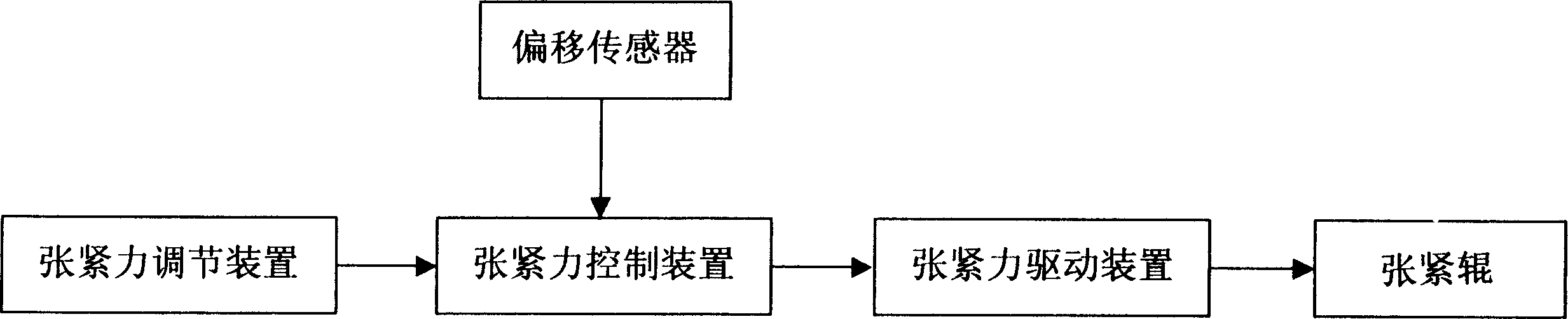
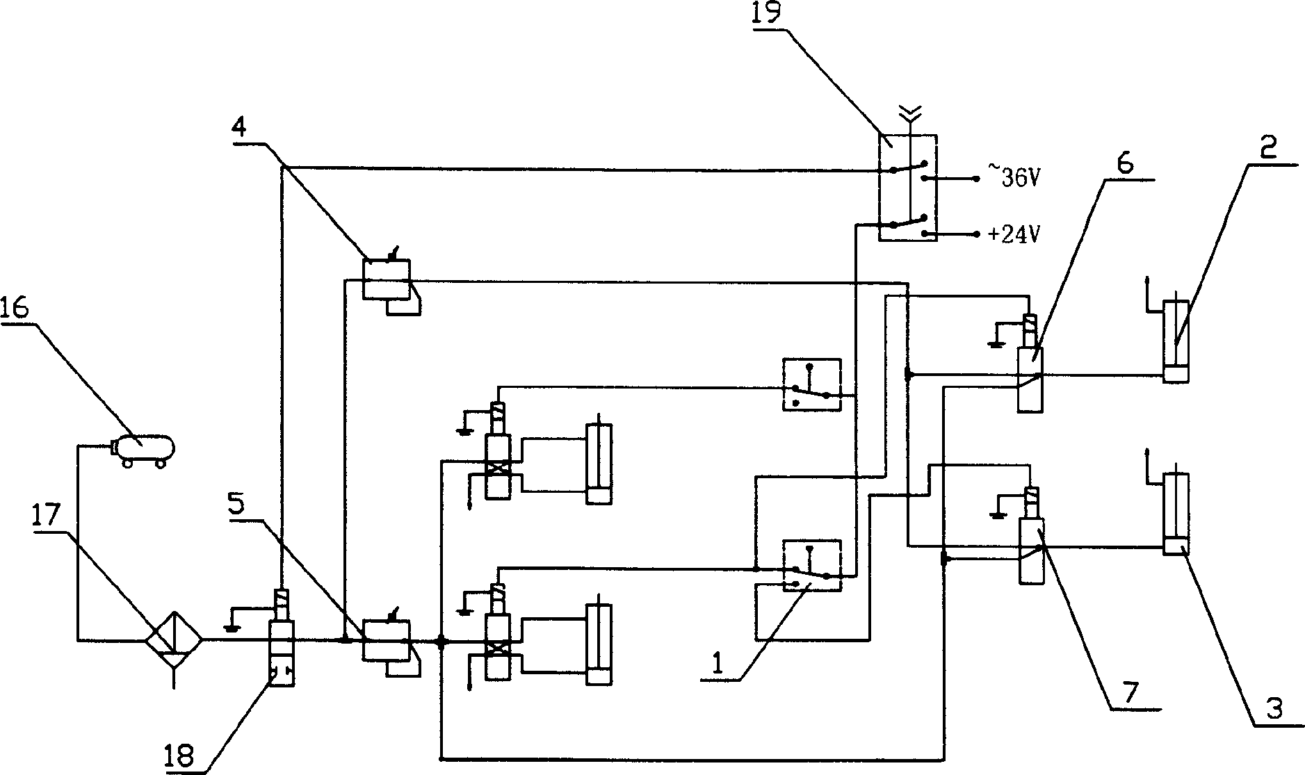
[0033] Embodiment 1 is a fixed-point adjustment device. Such as figure 1 Shown: belt-shaped moving object tension difference adjustment correction equipment, there are offset sensors, tension rollers and tension driving devices connected to both ends of the tension rollers, and tension control devices connected to the offset sensors. The tension adjusting device is connected with the tension driving device through the tension control device. The specific structure can be as figure 2 Shown: the offset sensor is the travel switch 1 arranged on the frame, the tension driving device is the cylinder 2, 3, the tension regulating device is the pressure reducing valve 4, 5, and the tension control device is Solenoid valve 6,7.

[0034] The specific connection mode is: the air compressor 16, the filter 17, the switch valve 18 are connected, the output of the switch valve 18 is connected with the pressure reducing valve 4,5 respectively, and the output of the pressure reducing valve...

Embodiment 2

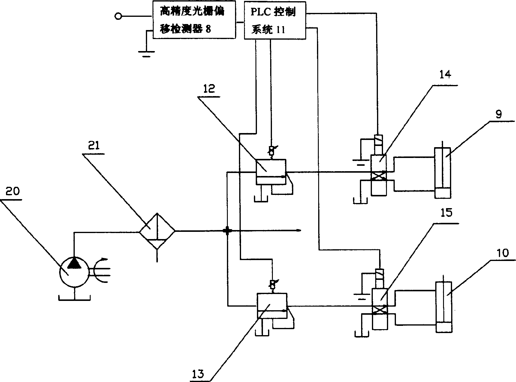
[0038] Embodiment 2 is a continuous adjustment device. Such as figure 1 Shown: belt-shaped moving object tension difference adjustment correction equipment, with offset sensor, and a tension control device connected to the offset sensor, the tension adjustment device is connected with the tension drive device through the tension control device catch. The specific structure can be as image 3 As shown: the offset sensor is a high-precision grating offset detector 8, the tension drive device is a hydraulic cylinder 9, 10, and the tension adjustment device is a PLC control system 11 and the PLC control system 11 The connected proportional pressure regulating valves 12, 13, the tension control device is the PLC control system 11 and the solenoid valves 14, 15 connected with the PLC control system 11.

[0039] The specific connection method is: after the quantitative pump 20 and the filter 21 are connected, they are respectively connected with the proportional pressure regulatin...


PUM


Abstract

The invention discloses a banding moving object tightening differential adjustment method, which comprises the following steps: monitoring bias condition of banding moving object and reducing tensile force of stretch roll in bias direction. The device comprises bias sensor, stretch roll and tensile force driving device connected with the two sides of stretch roll. Bias sensor connects control device of tensile force, via which tension-adjusting gear connects with tensile force driving device. Compared with existing technology, the greatest difference is that, according to bias condition of banding moving object, the invention adjusts tensile force of tension roll in time to ensure tensile force bias of the two sides and achieve correcting error. The invention has the advantages of simplicity of structure, low error rate, high reliability, no limitation of width of banding moving object, wide application area and so on.

Description

Technical field: [0001] The invention relates to a deviation-correcting method and equipment for a belt-shaped moving object, in particular to a method and equipment for adjusting the deviation-correcting tension difference of a belt-shaped moving object with simple structure, wide application range and good deviation-correcting effect. Background technique: [0002] At present, in metallurgy, chemical industry, printing, printing and dyeing, environmental protection and other industries, there is a belt movement process. For example, the sludge dehydration in the environmental protection industry uses a filter belt dehydrator with a belt movement process. The filter belt dehydrator uses upper and lower filter belts with strong water permeability. Through the gravity, pressing force and shear force between the two filter belts, the water in the mud is pressed out to achieve the purpose of sludge dehydration. The upper and lower filter belts are the moving belts. During the ...

Claims


Application Information

Patent Timeline
IPC IPC(8): B65H23/038
Inventor 祝冰
Owner 大连经济技术开发区排水管理有限公司
Why Eureka
Try Eureka