
Switch with optical controlling function
A dimmer switch and switch technology, applied in electric switches, electric selector switches, energy-saving control technology, etc., can solve problems such as user inconvenience and room darkening
- Summary
- Abstract
- Description
- Claims
- Application Information
AI Technical Summary
Problems solved by technology
Method used
Image

Examples
Embodiment 1
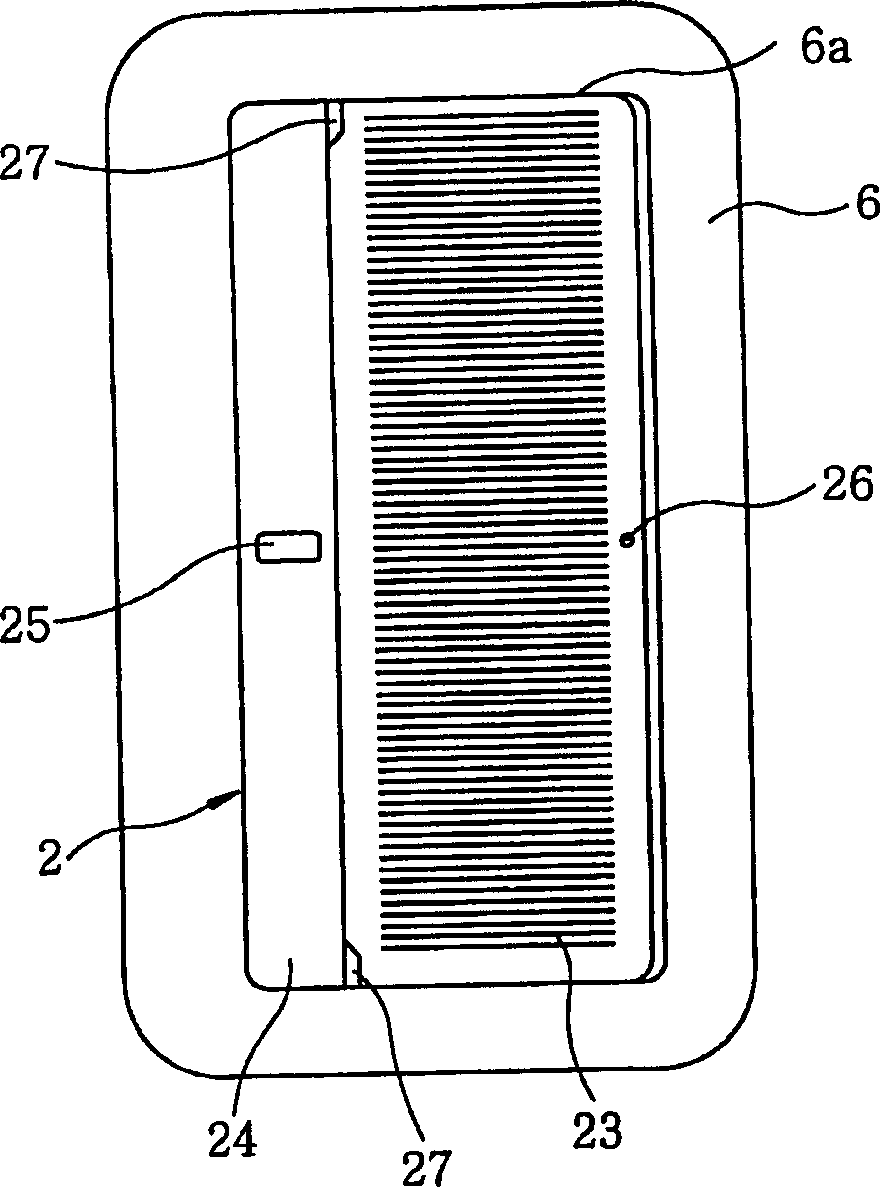
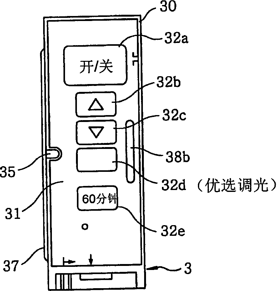
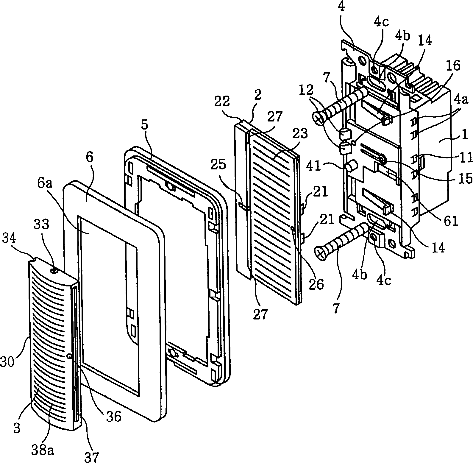
[0028] A first preferred embodiment of the present invention is described with reference to FIGS. 1 to 5 . Such as Figures 1A to 3 As shown in , the dimmer switch of this embodiment includes a substantially cuboid switch body 1 that is longer in the vertical direction than in the horizontal direction, a key actuating handle 2 that is pivotally connected to the switch body 1 , and detachably Be connected to the remote control main body (ie remote control main body) 3 on the key touch handle 2.
[0029] The switch main body 1 includes a printed circuit board (not shown) on which various circuit elements are mounted, such as constituting Figure 4A The button switch SW1, switch SW2, light emitting diode LD1, light receiving device 41, etc. of the electronic circuit system, the connecting terminal is configured as a conventional fast connecting terminal (not shown) for connecting the power line and the load line to the circuit board. In addition, a slit is formed around the rig...
Embodiment 2
[0058] refer to Figure 6 A second preferred embodiment of the present invention is described. In the second embodiment, the protrusion 39 protrudes toward the light receiving cover 24 from the side of the housing 30 of the remote control body 3 of the first embodiment, which side of the housing 30 faces the light receiving cover 24 . Moreover, the switch main body 1 includes an installed remote control detection switch SW4 for detecting whether the remote control main body 3 has been installed on the key touch handle 2 by detecting the existence of the protrusion 39 . Since the components of the dimmer switch according to this embodiment are similar or identical to those in the first embodiment except for the protrusion 39 and the installed remote controller detection switch SW4, the same reference numerals are assigned to the similar or identical , and its description will be omitted.
[0059] The installed remote controller detection switch SW4 may consist of a momentary ...
Embodiment 3
[0063] refer to Figure 7 A third preferred embodiment of the present invention is described. In the third embodiment, if the operation signal of the push button switch SW1 is input to the control circuit unit 40 multiple times within a predetermined period of time (for example, 2 seconds) through the multiple pressing operations of the key touch handle 2, the control circuit unit 40 operates as The reduced brightness turns on the brightness of lamp L to the dimming level pre-adjusted by the dimming control signal.
[0064] Regarding this embodiment, the same reference numerals are assigned to similar or identical components, and since the configuration and operation of this embodiment are similar to those of the first embodiment except for the control operation of the control circuit unit 40, description thereof will be omitted.
[0065] As described above, the control circuit unit 40 always monitors the operation input of the push button switch SW1. The control circuit uni...
PUM
 Abstract
Description
Claims
Application Information