

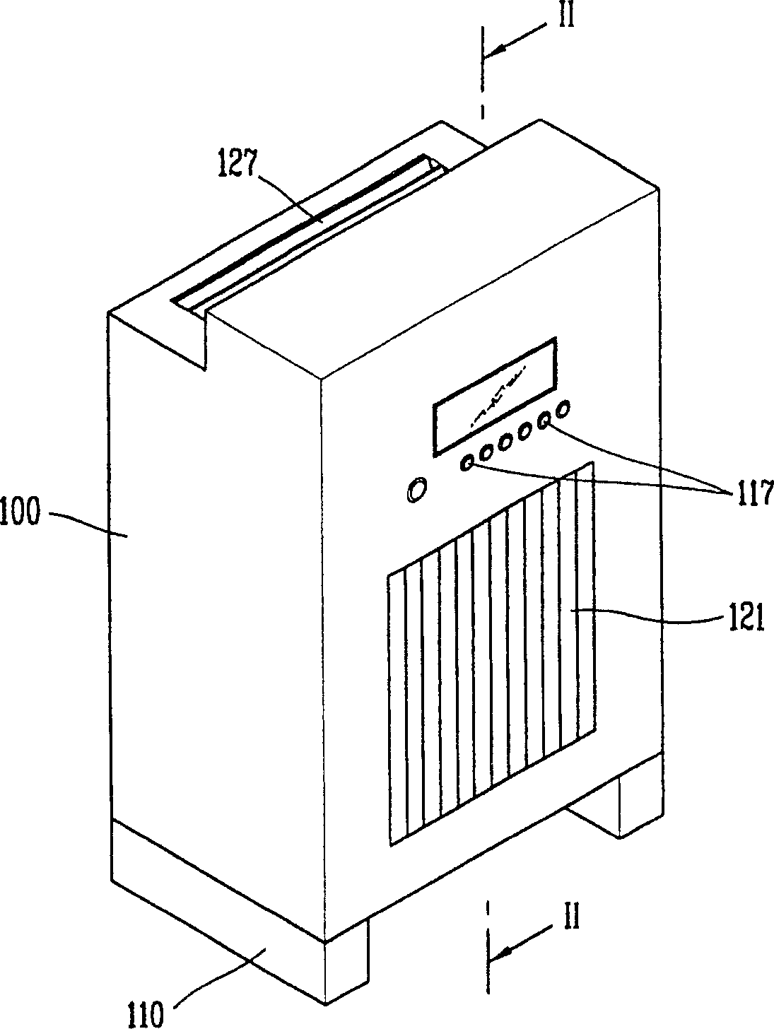
Centrifugal blower and air cleaner with the same
A technology for centrifugal fans and air purifiers, which can be applied to machines/engines, heating methods, mechanical equipment, etc., and can solve the problems of reducing centrifugal fans, not considering noise, and user discomfort.
- Summary
- Abstract
- Description
- Claims
- Application Information
AI Technical Summary
Problems solved by technology
Method used
Image

Examples
Embodiment Construction
[0029] Reference will now be made in detail to the preferred embodiments of the invention, examples of which are illustrated in the accompanying drawings.
[0030] Hereinafter, a centrifugal fan and an air cleaner including the same according to the present invention are explained in detail with reference to the accompanying drawings.
[0031] Although there are many preferred embodiments in the present invention, the most preferred embodiment will be described.
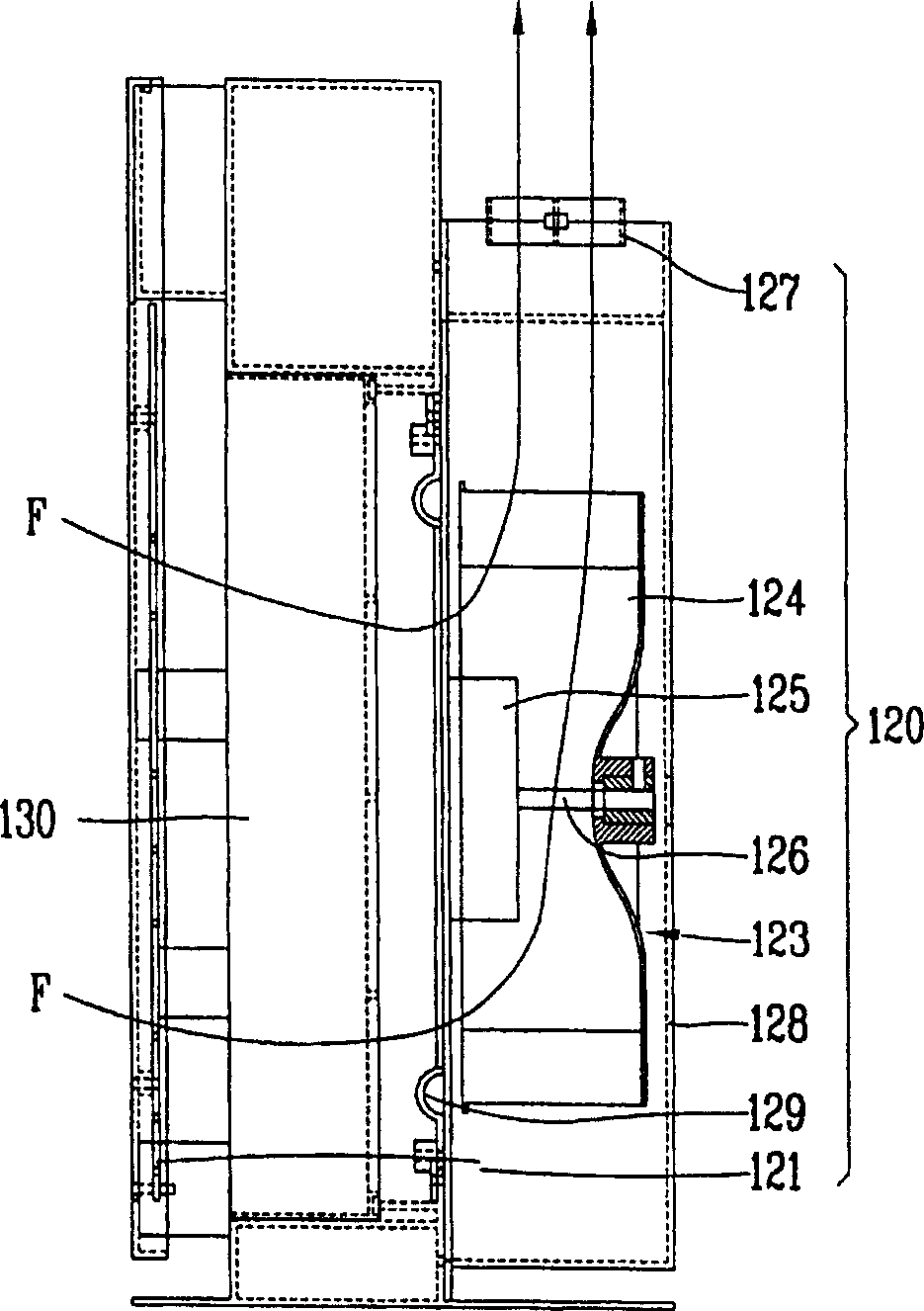
[0032] First, a centrifugal fan according to an embodiment of the present invention will be described in detail with reference to the accompanying drawings. use with Figure 1-3 The same reference numerals denote the present invention and the same descriptions are omitted.
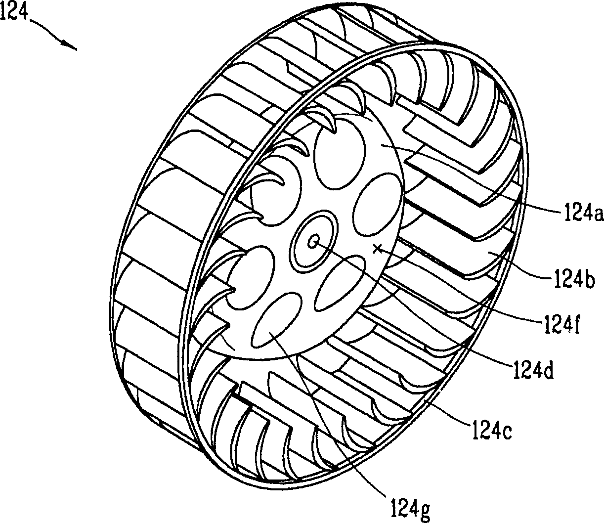
[0033] Figure 4A yes means image 3 The floor plan of the centrifugal fan, Figure 4B yes means image 3 side view of a centrifugal fan, and Figure 5 yes means image 3 A magnified view of the blade shown.
[0034] The blade 124b is fo...
PUM
 Abstract
Description
Claims
Application Information