Rail table system

A trolley system and trolley technology, applied in the field of systems, can solve problems such as cost increase and inability to solve stopping accuracy.

CN1931628BInactive Publication Date: 2011-07-06MURATA MASCH LTD
0 Cites 0 Cited by

Patent Information

Authority / Receiving Office
CN · China
Patent Type
Patents(China)
Current Assignee / Owner
Publication Date
2011-07-06
Estimated Expiration
Not applicable · inactive patent

Smart Images

  • Figure 1
    Figure 1
  • Figure 2
    Figure 2
  • Figure 3
    Figure 3
Patent Text Reader

Abstract

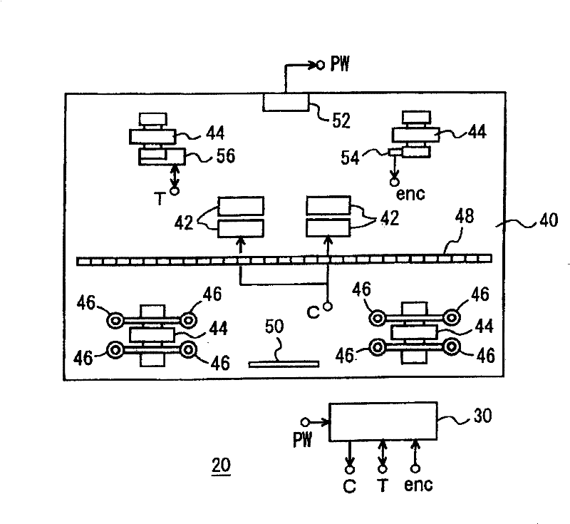
The present invention provides a track mounted jumbo system. In this system, a primary coil (10) of a linear synchronous motor is arranged at the fixing side in the vicinity of a station, and a magnet row (48) of the linear synchronous motor is arranged at a stacker crane (20). A primary coil (42) of a linear induction motor is arranged at the stacker crane (20), and a secondary conductor (8) is continuously arranged between the stations at the fixing side. The power of the linear induction motor is obtained from a non-contact electricity receiving part (52) by supporting the weight of the stacker crane (20) by a traveling wheel (44), and by supporting swiveling forces acting from the linear induction motor and the linear synchronous motor by a guide roller (46). The primary coil (10) is operated in the vicinity of the station by detecting a magnet position in the magnet row (48), and stopped by detecting an absolute position of the stacker crane (20) with respect to the station by a linear sensor (12).
Need to check novelty before this filing date? Find Prior Art

Description

technical field

[0001] The invention relates to systems such as stacking cranes or bridge cranes, rail trolleys traveling on the ground and the like. Background technique

[0002] We have already known a trolley system that uses a linear induction motor (LIM) to drive a trolley in a clean room or the like. The trolley system requires the trolley to travel at high speed over a long travel distance and to improve the accuracy of the stop position. LIM cannot solve the problem of stopping accuracy, and if a linear synchronous motor (LSM) is used instead, a problem of cost will arise. For example, the control of the LSM requires a linear sensor capable of detecting the position of the trolley, but if the linear sensor is installed along a long travel path, its cost will increase significantly. Contents of the invention

[0003] The object of the present invention is to use a simple system to enable rail trolleys to be transported over long distances, at high speeds, and with...

Examples

Embodiment

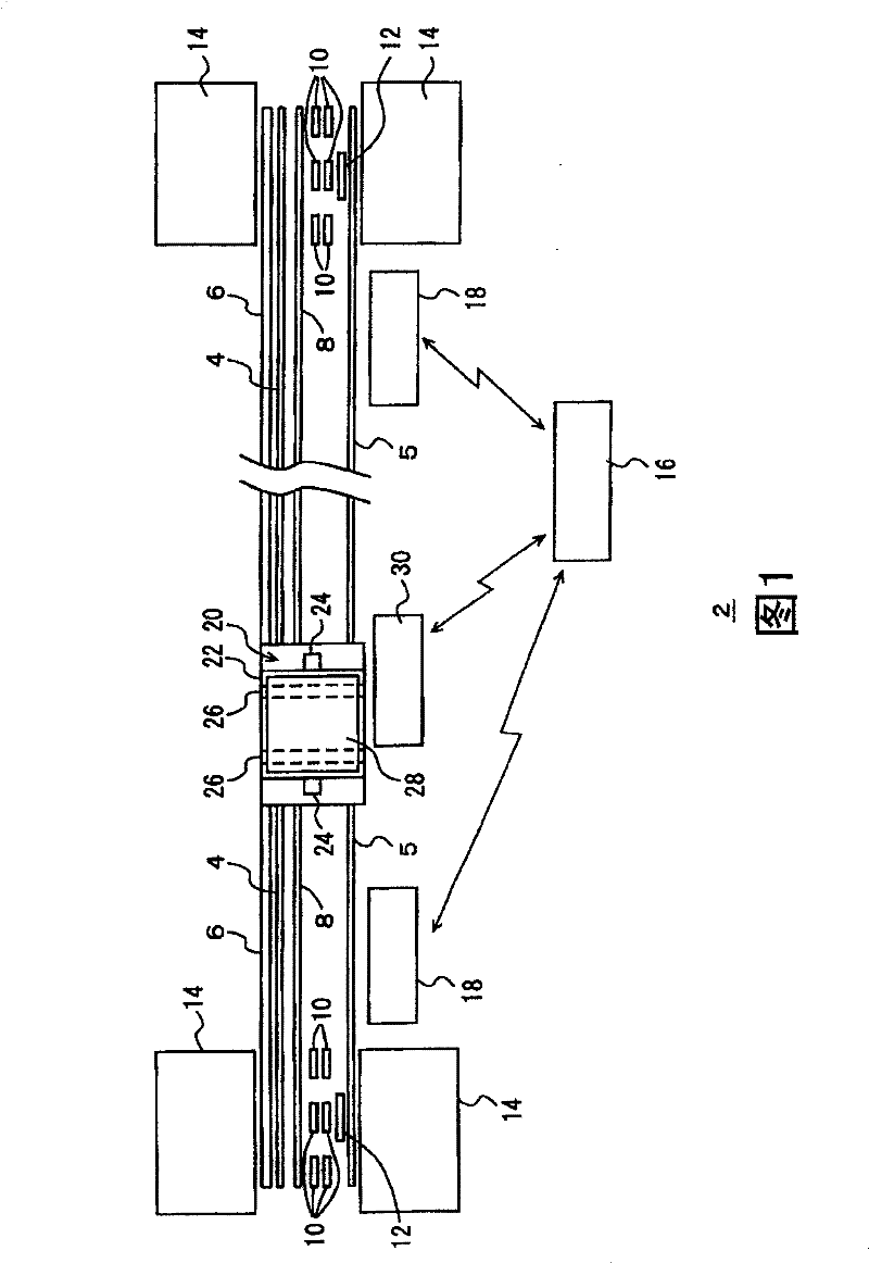
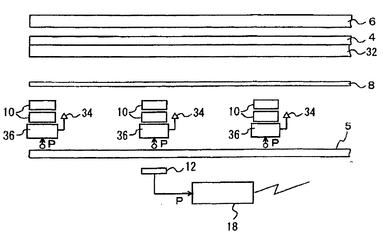
[0024] Figure 1 to Figure 8 Examples and modifications thereof are shown. In the figure, 2 is a trolley system, which can be regarded as a system for transporting boxes containing multiple liquid crystal substrates in a clean room. 4 and 5 are running rails, 6 is a power supply rail for non-contact power supply, 8 is a secondary conductor of a linear induction motor (LIM), and 10 is a primary coil of a linear synchronous motor (LSM). 12 is a linear sensor, which detects the absolute position of the stacking crane 20 relative to the stop position of the docking station 14 , and 16 is a control unit, which controls the entire rail trolley system 2 . In addition, 18 is a stop control means which controls the primary coil 10 of a linear synchronous motor etc. using the signal of the linear sensor 12 grade|etc.,.

[0025] 20 is a stacking crane, 22 is a lifting platform, which moves up and down along the mast 24, and uses a transfer mechanism 26 such as a sliding fork to transfe...