Embolic protection device and method

a protection device and a technology of embolic particles, applied in the field of embolic protection devices, can solve the problems of iatrogenic damage of the vessels in which they are positioned, neuropsychological deficits, stroke and even death, and thus embolishes the embolishes into the brain downstream, so as to alleviate or eliminate one or more deficiencies. , the effect of reducing the number of deficiencies

Active Publication Date: 2018-09-18
SWAT MEDICAL AB
View PDF10 Cites 8 Cited by
  • Summary
  • Abstract
  • Description
  • Claims
  • Application Information

AI Technical Summary

Benefits of technology

[0019]Accordingly, embodiments of the present disclosure preferably seek to mitigate, alleviate or eliminate one or more deficiencies, disadvantages or issues in the art, such as the above-identified, singly or in any combination by providing a device or method according to the appended patent claims for providing temporary embolic protection to a patient's aortic arch vessels during medical procedures, such as cardiac surgery and interventional cardiology and electrophysiology procedures. Embolic particles in the aortic blood flow are prevented from entering the aortic arch side branch vessels, including the carotid arteries that lead to the brain.

Problems solved by technology

Embolic particles, may include thrombus, atheroma and lipids, plaque found in the diseased vessels and valves that is dislodged and results in embolization.
Dislodged embolic particles can thus embolize into the brain downstream.
Cerebral embolism can lead to neuropsychological deficits, stroke and even death.
However, these devices may provide iatrogenic damage to the vessels in which they are positioned, e.g. by bows or arms extending into the side vessels of the aortic arch.
The bows or arms provide anchoring in the arch, but increase risk of scraping off embolic particles, in particular from around the ostia to the side vessels.
The devices also have a rather high profile in the aortic arch, limiting the endovascular procedures to be performed through the arch.
However, this leads potentially to so-called wind sucker disadvantages due to the movement of the aorta with every heart beat.
Debris may collect at the edge of the umbrella and be occasionally sucked into the side vessel as the hub is locked when pulled back and does not follow the aorta movement sufficiently well.
Embolic protection efficiency is thus not optimal of the devices described in WO2012009558.
The device blocks the aortic arch when in position and does not allow for index procedures to be performed in a femoral approach.
However, the device is complicated as no blood can flow directly from the aortic arch to the side vessels and extracorporeal blood handling devices are needed.
One issue is that blood, that may include embolic particles, may impair efficiency of the devices by bypassing across the device at the periphery thereof to the carotid arteries due to insufficient sealing at the periphery.

Method used


Image

  • Embolic protection device and method
  • Embolic protection device and method
  • Embolic protection device and method

Examples


Embodiment Construction

[0098]Specific examples will now be described with reference to the accompanying drawings. This invention may, however, be embodied in many different forms and should not be construed as limited to the embodiments set forth herein; rather, these embodiments are provided so that this disclosure will be thorough and complete, and will fully convey the scope of the invention to those skilled in the art. The terminology used in the detailed description of the embodiments illustrated in the accompanying drawings is not intended to be limiting of the invention. In the drawings, like numbers refer to like elements.

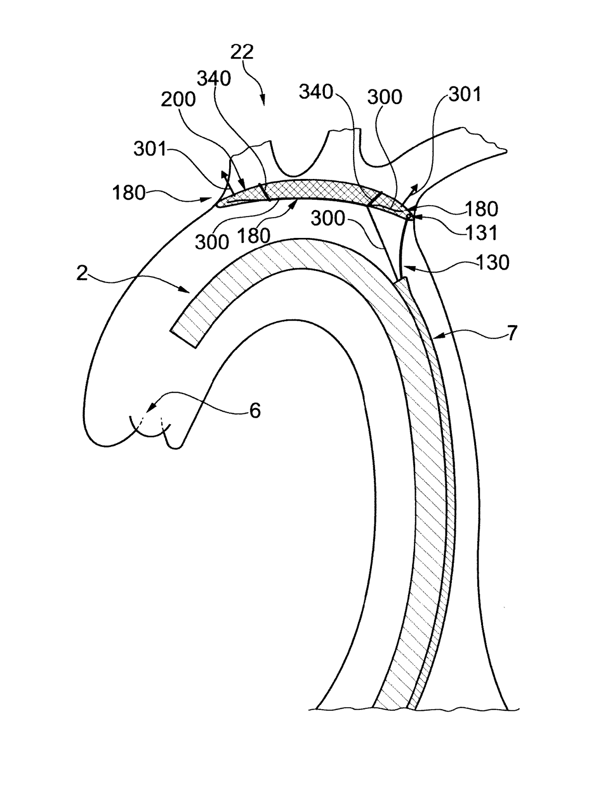
[0099]FIG. 1 shows a schematic illustration of an aortic arch 100 and a plurality of side branch vessels, including a third side branch vessel 116, a second side branch vessel 118, and a first side branch vessel 120. The aortic valve 6 is illustrated in some of the Figs. Normally, three branches of the aorta split off from the trunk of the aortic arch 100 in three separate ostia....


PUM


Abstract

A collapsible, transluminally deliverable embolic protection device (200) for temporarily positioning in the aortic arch is disclosed. The device is connectable to a transluminal delivery unit (130) extending proximally from a connection point (131). The device has a frame with a periphery, and a blood permeable unit within said periphery for preventing embolic particles from passing therethrough into side vessels of said aortic arch to the brain of a patient. Further, the device has at least one tissue apposition sustaining unit, not being a delivery shaft of said device, for application of a force offset to said connection point at said device, such as at said periphery, towards an inner wall of said aortic arch when said device is positioned in said aortic arch, such that tissue apposition of said periphery to an inner wall of said aortic arch is supported by said force. In addition related methods are disclosed.

Description

RELATED APPLICATIONS[0001]This application is the U.S. National Phase of and claims priority to International Patent Application No. PCT / EP2013 / 073895, International Filing Date Nov. 14, 2013, entitled Improved Embolic Protection Device And Method, which claims benefit of European Patent Application No. EP12192690.1, filed Nov. 14, 2012 entitled Improved Embolic Protection Device And Method; and U.S. Provisional Application Ser. No. 61 / 726,537, filed Nov. 14, 2012 entitled Improved Embolic Protection Device And Method; all of which are incorporated herein by reference in their entireties.BACKGROUND OF THE INVENTION[0002]Field of the Invention[0003]This invention pertains in general to the field of embolic protection devices. More particularly the invention generally relates to systems and methods for cerebral protection by deflection of embolic debris, such as during an endovascular procedure, in particular on the heart, in some embodiments.[0004]Description of Prior Art[0005]This s...

Claims


Application Information

Patent Timeline
Patent Type & Authority Patents(United States)
IPC IPC(8): A61M29/00A61F2/01
CPCA61F2002/018A61F2250/0059A61F2230/0008A61F2/011A61F2002/016A61F2/01
Inventor KRAHBICHLER, ERIK
Owner SWAT MEDICAL AB
Why Eureka
Try Eureka