Temporary Embolic Protection Device And Medical Procedure For Delivery Thereof

a technology of embolism protection and medical devices, applied in the field of medical devices and medical procedures, can solve the problems of stroke, death, and device damage to the implantation site, and achieve the effect of alleviating, eliminating or mitigating one or more deficiencies

Active Publication Date: 2014-09-11
SWAT MEDICAL AB
View PDF9 Cites 5 Cited by
  • Summary
  • Abstract
  • Description
  • Claims
  • Application Information

AI Technical Summary

Benefits of technology

This patent describes a device or method that helps protect the blood vessels in a patient's aortic arch during medical procedures. It prevents particles from entering the vessels and potentially causing harm, especially in the brain. This technology aims to improve patient safety during medical procedures.

Problems solved by technology

Embolic particles, which may include thrombus, atheroma and lipids, may become dislodged by surgical or catheter manipulations and enter the bloodstream, embolizing in the brain or other vital organs downstream.
Cerebral embolism can lead to neuropsychological deficits, stroke and even death.
However, the embolic protection devices disclosed in 2004 / 0215167 have a number of drawbacks.
The device may be difficult to extract from the aortic arch as a stent like design is devised for permanent implantation and removing a stent may harm the implantation site.
However, this debris is an undesired embolic material, which the device should avoid to enter the branch vessels.
However, like the devices disclosed in US 2004 / 0215167, the devices and methods of U.S. Pat. No. 6,258,120 may damage the aortic vessel wall.
Furthermore, a leakage of embolic material into the side branch vessels of the aortic arch may be present, e.g. past the periphery of the tubular structure, or of the snowshoe like embodiments disclosed.
Moreover, the devices disclosed may, at least partly, contact the ostia of the side branch vessels, and thus set free embolic debris from the ostia which is carried to the carotid arteries and may lead to cerebral damage.
The snowshoe like devices have and attached handle or cannula and need to be installed by means of open chest surgery comprising incising the aorta, which has numerous drawbacks compared to intravascular delivery, including aortic trauma.
Such securing is difficult to accomplish in a reliable manner via transvascular access.
This means that, like in the aforementioned disclosures, the device will inevitably be intravascularly manipulated and thus it will likely contact the ostia of the brachiocephalic artery, i.e. the side branch vessel of the aorta leading to the right carotid artery.
Thus a risk for iatrogenic caused embolization is present, i.e. the physician likely will set free embolic debris from the ostia of the brachiocephalic artery when using the device.
The embolic debris is carried to the right carotid artery and may lead to cerebral damage.
Moreover, the dome shaped device of US 2008 / 0065145 appears to be difficult, to work in practice due to the anatomical structure and position of the afore described access way via the brachiocephalic artery.
Thus the device will be very voluminous in the aortic arch.
Hence, known cerebral embolic protection devices have shortcomings, including: difficult to position in a vessel, and even more difficult to position in two vessels; they may cause damage to the vessel wall and potentially cause an emboli themselves; they are hindering surgeons when trying to achieve a good result with some intended intervention / operation; visualization of the protective device may impair visualization of other components used during concurrent medical procedures; they may cause impaired flow if they are designed to collect the embolic material.

Method used


Image

  • Temporary Embolic Protection Device And Medical Procedure For Delivery Thereof
  • Temporary Embolic Protection Device And Medical Procedure For Delivery Thereof
  • Temporary Embolic Protection Device And Medical Procedure For Delivery Thereof

Examples


Embodiment Construction

[0081]Specific embodiments of the invention will now be described with reference to the accompanying drawings. This invention may, however, be embodied in many different forms and should not be construed as limited to the embodiments set forth herein; rather, these embodiments are provided so that this disclosure will be thorough and complete, and will fully convey the scope of the invention to those skilled in the art. The terminology used in the detailed description of the embodiments illustrated in the accompanying drawings is not intended to be limiting of the invention. In the drawings, like numbers refer to like elements.

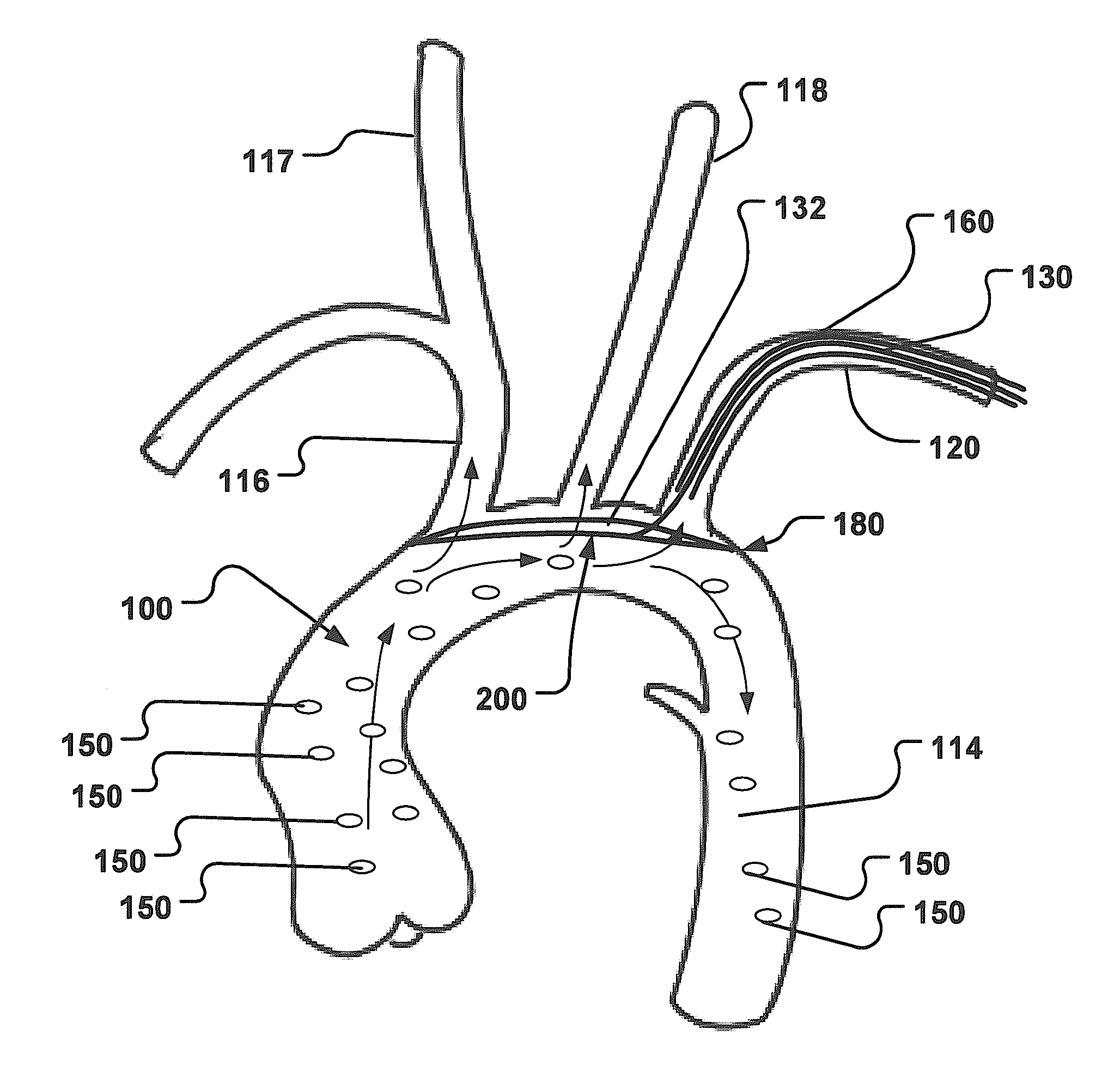
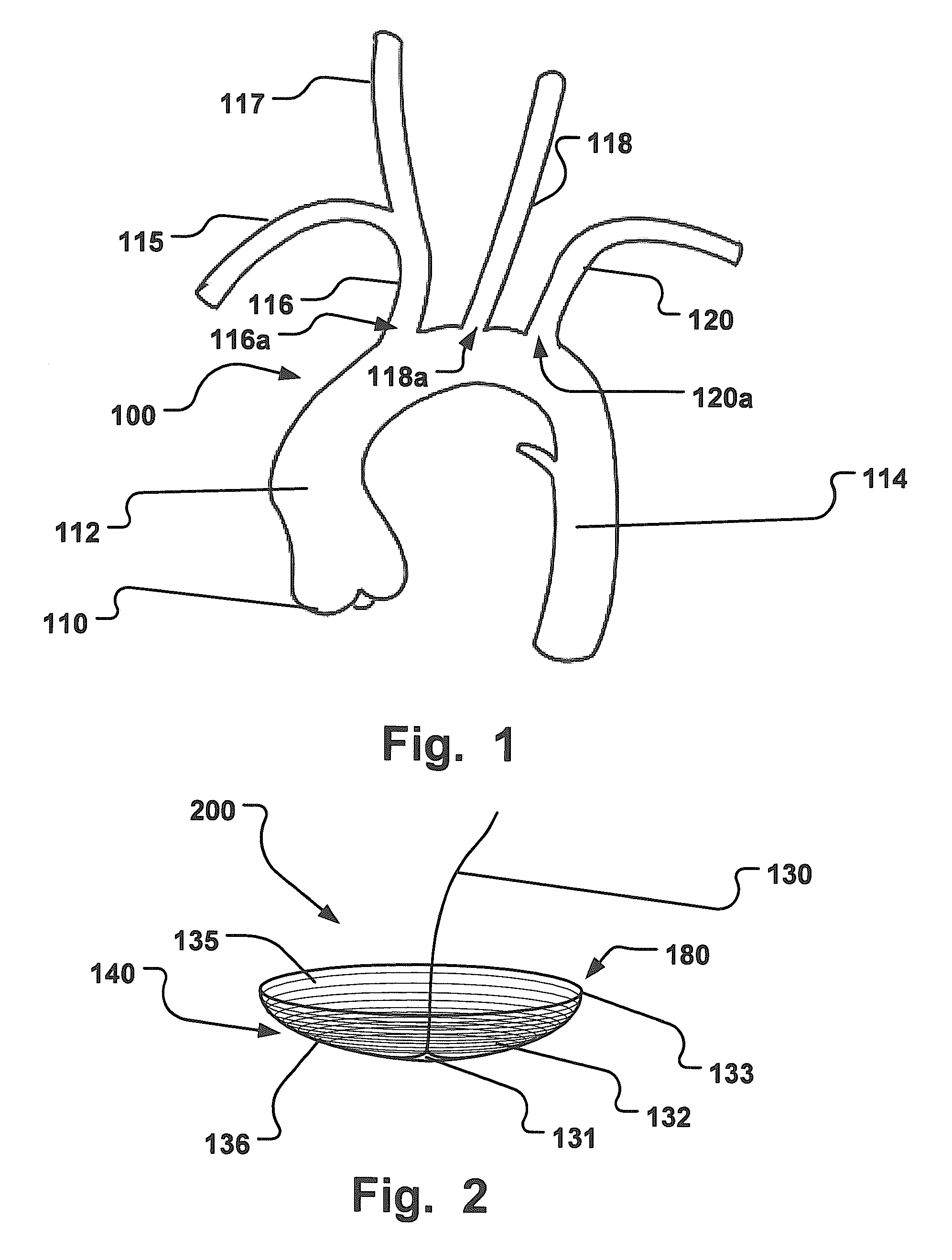
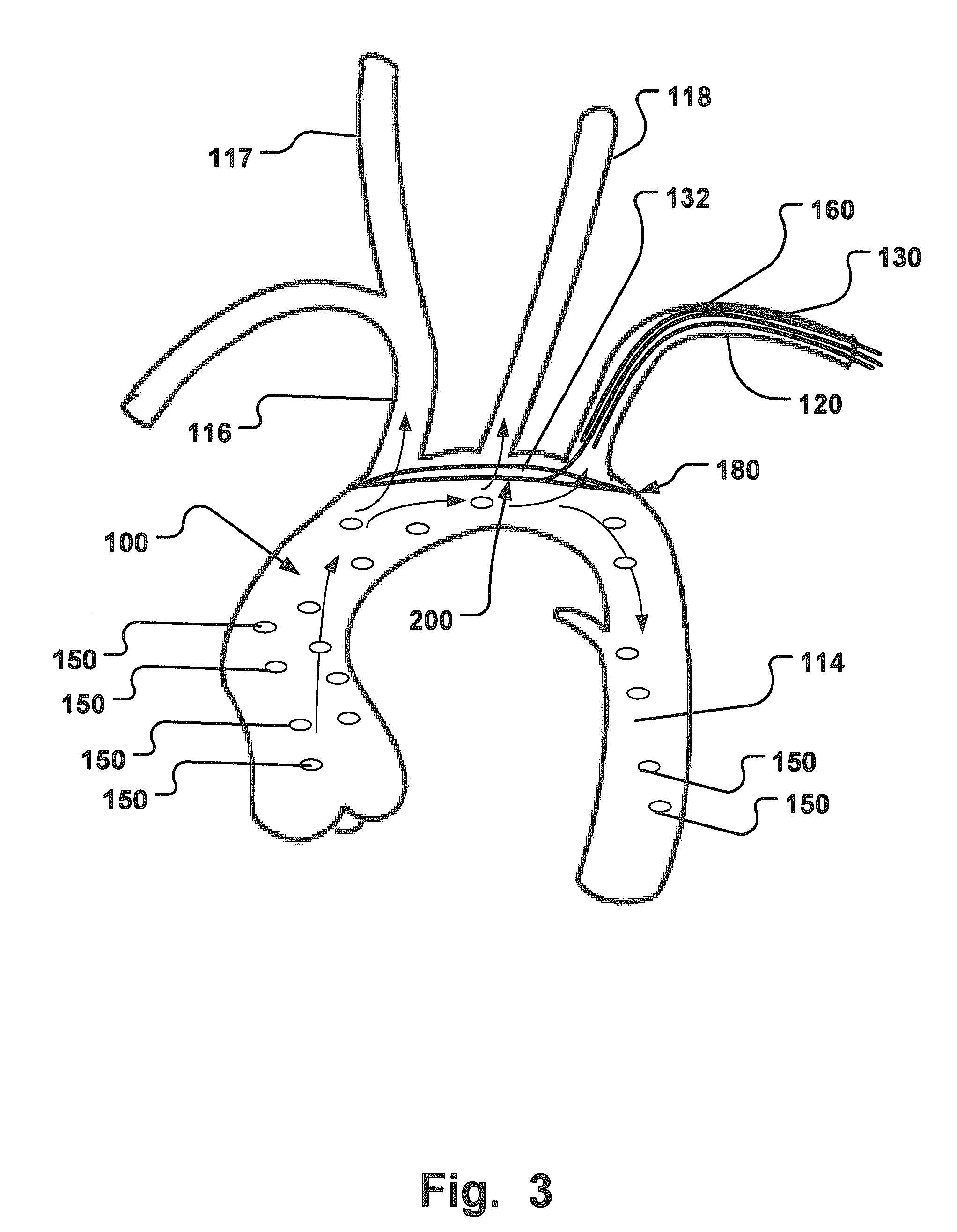
[0082]In order to get a better understanding of the anatomical situation in which the present invention is carried out, FIG. 1 shows a schematic illustration of an aortic arch 100 and a plurality of side branch vessels, including a third side branch vessel 116, a second side branch vessel 118, and a first side branch vessel 120.

[0083]The aortic arch 100 descri...


PUM


Abstract

An embolic protection device and medical procedure for positioning the device in the aortic arch is disclosed. The device and method effectively prevent material from entering with blood flow into side branch vessels of the aortic arch. The device is a collapsible embolic protection device devised for temporary transvascular delivery to an aortic arch of a patient, wherein the device has a protection unit that comprises a selectively permeable unit adapted to prevent embolic material from passage with a blood flow into a plurality of aortic side branch vessels at the aortic arch. The protection unit is permanently attached to a transvascular delivery unit at a connection point provided at the selectively permeable unit, and a first support member for the protection unit that is at least partly arranged at a periphery of the selectively permeable unit. In an expanded state of the device, the connection point is enclosed by the first support member or arranged at said support member.

Description

RELATED APPLICATIONS[0001]This application is a continuation of U.S. patent application Ser. No. 13 / 848,673 filed Mar. 21, 2013 entitled Temporary Embolic Protection Device And Medical Procedure For Delivery Thereof; which is a continuation of U.S. patent application Ser. No. 13 / 062,499, 371(c) date Aug. 16, 2011, entitled Temporary Embolic Protection Device And Medical Procedure For Delivery Thereof; which is a U.S. National Stage Application of and claims priority to International Patent Application No. PCT / EP2009 / 061509, International Filing Date 4 Sep. 2009, entitled Temporary Embolic Protection Device And Medical Procedure For Delivery Thereof; which claims priority to Swedish Patent Application 0801901-0 filed 4 Sep. 2008 entitled Embolic Protection Device And Medical Procedure For Delivery Thereof, and to U.S. Provisional Application Ser. No. 61 / 094,283 filed 4 Sep. 2008 entitled Embolic Protection Device And Medical Procedure For Delivery Thereof; all of which are hereby inc...

Claims


Application Information

Patent Timeline
Patent Type & Authority Applications(United States)
IPC IPC(8): A61B17/12
CPCA61B17/12109A61B17/12036A61B2017/1205A61B17/12159A61B17/1204A61F2002/018A61F2230/0008A61F2230/0093A61F2230/0076A61F2230/0069A61F2/013A61F2/02A61M29/00A61B17/12A61F2/00A61F2/0063A61F2002/0068A61B17/12172
Inventor JONSSON, ANDERS
Owner SWAT MEDICAL AB
Why Eureka
Try Eureka