Apparatus and method for detecting the current damaged state of a machine

a technology of current damage and apparatus, applied in the direction of electric programme control, program control, instruments, etc., can solve the problems of blades being subject to high mechanical, aerodynamic and thermal loads, unwarranted damage of blades, total loss during the course of further operation of the machine, etc., to improve the availability and communication

Active Publication Date: 2018-10-02
SIEMENS ENERGY GLOBAL GMBH & CO KG
View PDF12 Cites 0 Cited by
  • Summary
  • Abstract
  • Description
  • Claims
  • Application Information

AI Technical Summary

Benefits of technology

[0011]The following renders it possible to quickly identify simple damage, in particular the initial damage to a machine, in particular on the blades of a gas turbine. Hence, a further development of this initial damage to total loss can be stopped in a quick and reliable manner. By way of embodiments of the invention, it is furthermore possible to avoid cost-intensive repairs as relatively small initial damage can usually be rectified with less outlay. The intended / actual comparison (alternatively “intended / actual comparison” throughout the specification means “a comparison of or between the intended to actual”) carried out by the device supplies a simple, analog characteristic, which can be transferred to the process control system of the installation and observed by simple threshold monitoring. Advantageously, a robust device according to embodiments of the invention are obtained, which is independent of other parameters (e.g. the operating states of the machine such as load, ambient conditions, etc.).
[0013]Preferably, the data detection and processing apparatus generates an intended cepstrum with the aid of an undamaged machine, from which the intended cepstrum value agreeing with the actual cepstrum value is then determinable. As a result, a suitable intended cepstrum value can be determined very easily.
[0015]Preferably, a machine unit is provided, which initiates an emergency operation if a predefined threshold of the intended / actual comparison is exceeded. As a result, time for introducing an emergency operation is saved. Hence, total loss may possibly be avoided.
[0017]Preferably, the machine is a compressor with rotor blades and a rotor. In a preferred refinement, the compressor comprises a compressor circumference and a compressor outlet, wherein the plurality of pressure sensors are attached over the compressor circumference at the compressor outlet. This serves the plausibility, to improve the availability and the communication of the detected flow parameters over the circumferential coordinate.
[0018]Preferably, the compressor comprises a compressor circumference and the pressure sensors are not attached below these rotor blades on the compressor circumference. This would lead to large pressure amplitudes, which would have an inexpedient effect on the device.
[0019]In a preferred refinement, the rotor has a rotary frequency. Preferably, the minimum bandwidth of the data detection and processing apparatus emerges from the maximum number of rotor blades multiplied by twice the rotary frequency of the rotor. Using this, the spectra and the cepstra can be detected correctly.

Problems solved by technology

When the machine is in operation, these blades are subject to high mechanical, aerodynamic and thermal loads.
These loads can lead to unwanted damage of the blades.
The specific problem existing here has initially only little damage at a single blade being able ultimately to lead to total loss during the course of the further operation of the machine.
Therefore, the pressing problem lies in identifying the small initial damage, which may have multifaceted causes and characteristics, during the operation of the machine and being able to derive a warning.
As a result, damage is also identifiable / derivable directly from the actual cepstrum value.
This would lead to large pressure amplitudes, which would have an inexpedient effect on the device.

Method used


Image

  • Apparatus and method for detecting the current damaged state of a machine
  • Apparatus and method for detecting the current damaged state of a machine
  • Apparatus and method for detecting the current damaged state of a machine

Examples


Embodiment Construction

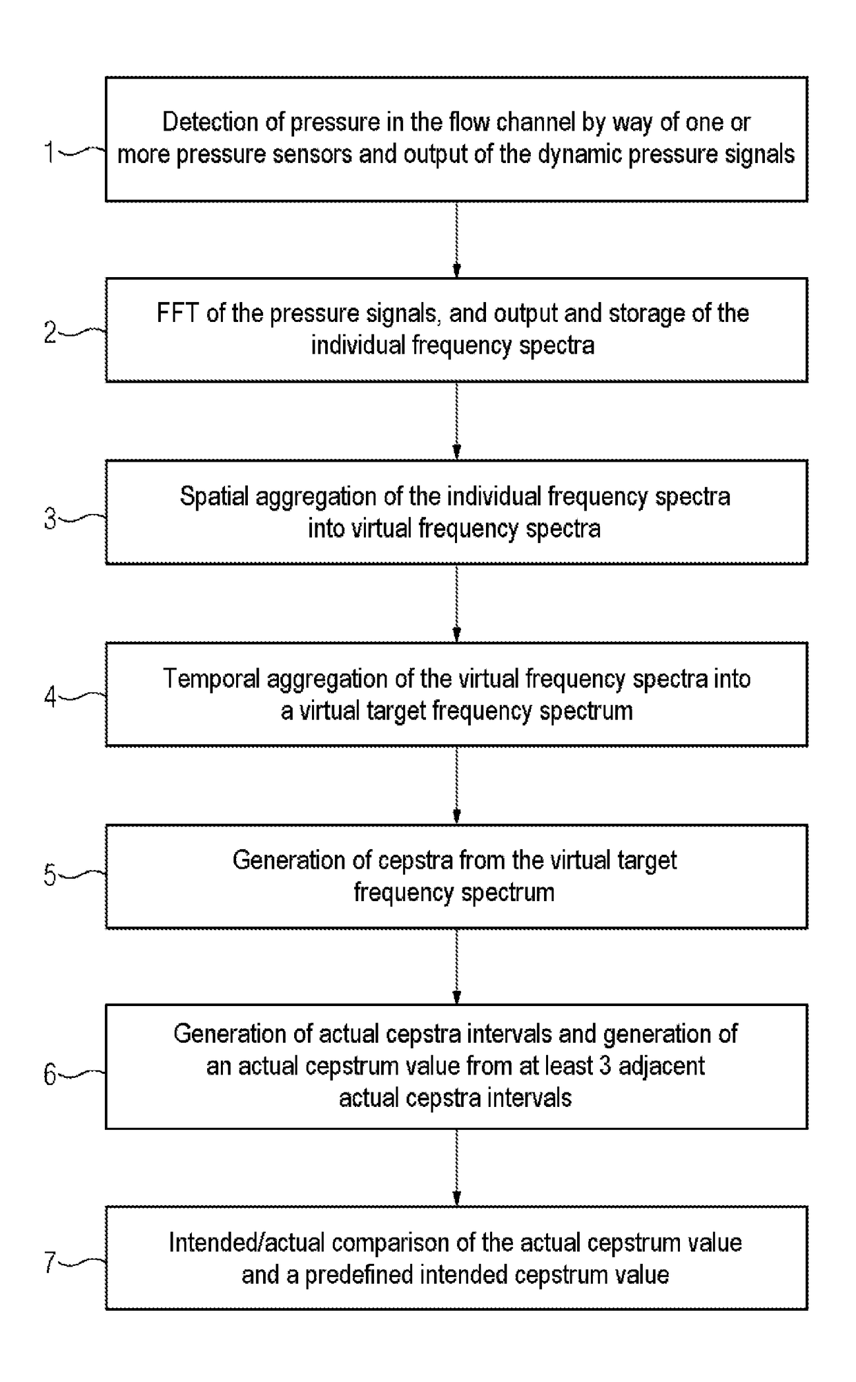
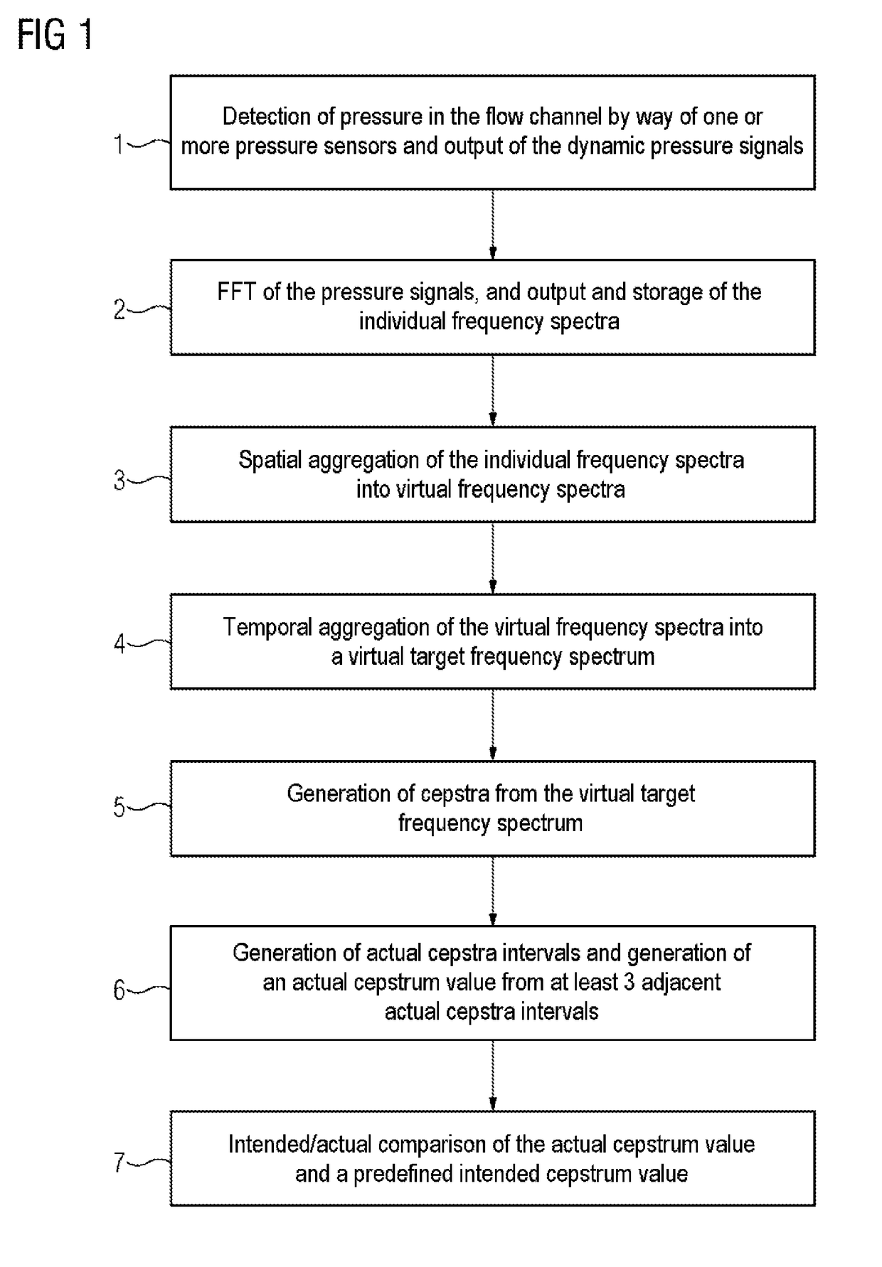
[0037]FIG. 1 schematically shows the method. Here, suitable pressure sensors for detecting the current state of damage are arranged in a machine. Without loss of generality, a compressor is used as a machine below. Dynamic pressure sensors are arranged in the flow channel in the compressor, in particular in the axial compressor of a gas turbine. Here, the placement of the pressure sensors is directed to the desired detection sensitivity. Advantageously, a plurality of these pressure sensors, i.e. measurement locations, is arranged along the circumference of the outlet of the compressor with an identical longitudinal coordinate. This serves the plausibility, to improve the availability and the communication of the detected flow parameters over the circumferential coordinate. It is advantageous if the pressure sensors are not attached to those walled regions over which rotor blades pass directly. This would lead to large pressure amplitudes, which could interfere with the intended ana...


PUM


Abstract

A method and apparatus for detecting the current damaged state of a machine is provided. The disclosed relates to an apparatus for detecting the current damaged state of a machine, wherein the data capture and editing device: comprises a Fast Fourier analysis apparatus, for performing a transformation from pressure signals that are available in the time domain to a frequency domain as discrete-time frequency spectra (2), additionally includes a spatial aggregation unit and a temporal aggregation unit that combines the discrete-time frequency spectra, additionally includes a cepstrum analysis unit, for producing a cepstrum with various actual cepstrum values from the temporally and spatially aggregated discrete frequency spectra (5), additionally includes a computation unit that takes the cepstra produced in this manner and produces, at a previously defined interval of time, a plurality of actual cepstrum intervals including adjacent actual cepstrum values, as a result of which an actual cepstrum value, which can be ascertained from at least three adjacent actual cepstrum intervals, can be produced (6), includes a unit that computes (7) a target / actual comparison with the actual cepstrum value produced in this manner and a previously determined target cepstrum value.

Description

CROSS-REFERENCE TO RELATED APPLICATIONS[0001]This application claims priority to PCT Application No. PCT / EP2014 / 073098, having a filing date of Oct. 28, 2014, based off of DE Application No. 102013226049.0 having a filing date of Dec. 16, 2013, the entire contents of which are hereby incorporated by reference.FIELD OF TECHNOLOGY[0002]The following relates to all general machines which are embodied as turbomachines, such as e.g. flow machines, gas turbines, compressors, turbochargers or aero engines.BACKGROUND[0003]Turbomachines such as e.g. gas turbines are characterized in that they consist of multi-stage compressor and turbine components. Here, a compressor or turbine stage includes a stationary stator blade row and a rotating rotor blade row. The stator blade and rotor blade row consists of a multiplicity of individual blades. Therefore, an overall machine includes several hundred stator and rotor blades. When the machine is in operation, these blades are subject to high mechanic...

Claims


Application Information

Patent Timeline
Patent Type & Authority Patents(United States)
IPC IPC(8): G05B19/406G05B19/416G01H1/00G05B23/02G01M7/00
CPCG05B19/406G01H1/006G01M7/00G05B23/024G05B19/416G05B2219/37399G05B2219/37371
Inventor BRUMMEL, HANS-GERDPFEIFER, UWE
Owner SIEMENS ENERGY GLOBAL GMBH & CO KG
Why Eureka
Try Eureka