Method for determining a torque acting on a rotational device or a force acting on a rotational device

a technology of rotational devices and torques, applied in the direction of force sensors, instruments, force/torque/work measurement apparatus, etc., can solve the problems of air bearing damage very quickly, avoid damage to rotary apparatuses, and reduce the deflection of rotors

Active Publication Date: 2019-12-10
CARL ZEISS IND MESSTECHN GMBH
View PDF33 Cites 0 Cited by
  • Summary
  • Abstract
  • Description
  • Claims
  • Application Information

AI Technical Summary

Benefits of technology

[0012]The particular advantage of the invention lies in the fact that the torque is ascertainable in only one rotational position of the rotary apparatus or of a rotor of the rotary apparatus. Hence, no rotation of movable parts of the rotary apparatus, in particular of a rotor, is required. The method may occur without rotational movement.
[0013]If use is made of at least three detection devices, it is possible to determine a deflection, and the tilting moment and / or position error therefrom in a next step, in each rotor position or rotational position and in only exactly one such rotational position. By avoiding a rotation, it is possible to avoid damage to a rotary apparatus, in particular a rotary bearing, which would be the consequence of overloading parts of the rotary apparatus, if a torque is applied. This is particularly advantageous in the case of a sensitive bearing of the rotor, for example in the case of an air bearing. Air bearings may be damaged very quickly if they are overloaded by an excessive tilting moment on the borne rotor shaft. It is possible to ascertain the deflection and, therefrom, a tilting moment and / or position error in one rotational position without requiring a rotational movement or the setting of one or more further rotational positions, in the case of which a sensitive bearing could be damaged.
[0014]The terms “moment” and “torque” are used synonymously. A moment or torque directed across, in particular perpendicular to, an axis of rotation of a rotary apparatus is also referred to as “tilting moment”. The phrase “tilting moment” is derived from the fact that a suitable force acting on the rotary shaft externally, which causes a torque across the axis of rotation, causes a greater or smaller deflection of the rotor in the form of a tilt. By way of example, the force is the weight of a workpiece which, with the center of gravity thereof, is positioned away from the axis of rotation of a rotor, as a result of which the rotor is deflected, in particular tilted, across the axis of rotation, in other words laterally, as a result of the weight. Tilting moments may also arise by centrifugal forces during the rotation of a rotor of a rotary apparatus.
[0015]A “deflection” of the rotor means that the rotor is rotated about a rotational axis which is at an angle to the axis of rotation of the rotor. Expressed differently, the deflection is a rotational movement of the rotor about a rotational axis which is at an angle to the provided axis of rotation of the rotor (also referred to as a tilt or a rotational deflection). The rotational axis at an angle to the axis of rotation of the rotor is preferably a virtual axis, i.e. not a physically embodied rotary shaft.
[0016]The torque may be expressed by the cross productM=r×F where F for example denotes the weight produced by a mass positioned on the rotary apparatus, said weight being directed parallel to the axis of rotation, or a force component parallel to the axis of rotation, andr for example denotes the radial distance of the center of gravity of the mass from the axis of rotation.
[0017]The torque acts on the rotary shaft and / or on a part of the rotary apparatus rotatable about the axis of rotation, in particular a rotor and / or a measuring body or detection devices of a measuring system.

Problems solved by technology

Air bearings may be damaged very quickly if they are overloaded by an excessive tilting moment on the borne rotor shaft.

Method used


Image

  • Method for determining a torque acting on a rotational device or a force acting on a rotational device
  • Method for determining a torque acting on a rotational device or a force acting on a rotational device
  • Method for determining a torque acting on a rotational device or a force acting on a rotational device

Examples


Embodiment Construction

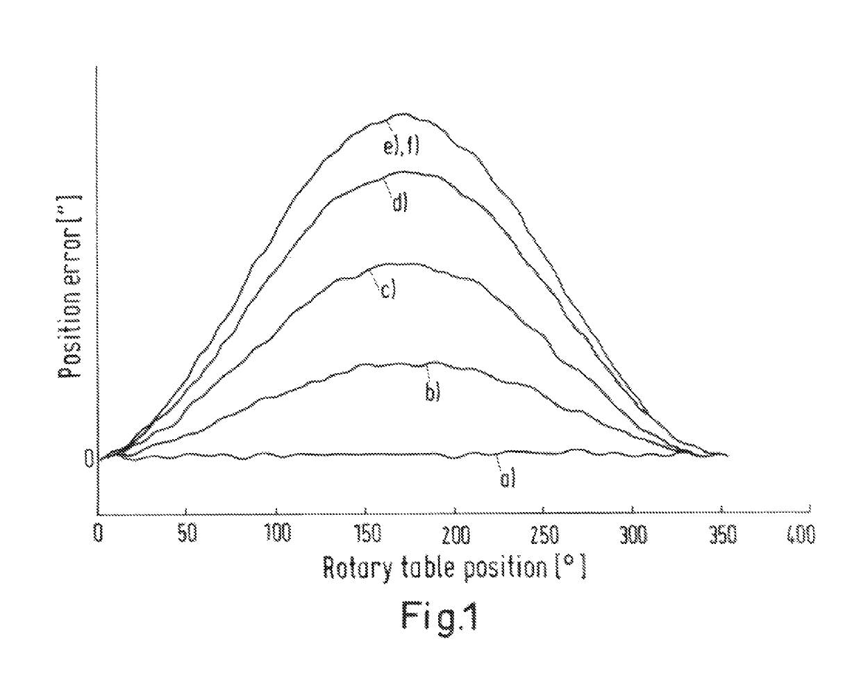
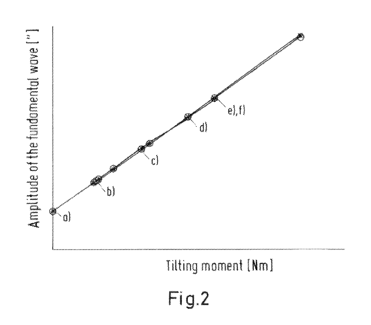
[0174]1. General Considerations.

[0175]Tilting moments acting on the rotor of the rotary shaft cause a tilt of the rotor. Since a lever is usually present between rotational point (bearing site) and standard, the tilt causes an eccentricity of the standard. An eccentricity of the standard causes a so-called eccentric error in the measured angle positions. The position error is greatest if the displacement of the standard is perpendicular to the angle sensor or reading head, and may be calculated as follows:

α=s / r

where α=position error,[0176]s=eccentric amplitude[0177]r=radius of the standard

[0178]Trials have shown that the relationship between the amplitude of the so-called eccentric error and the causative tilting moment is often good-natured and, for example, describable by a straight line or a polynomial. The trials were carried out using a rotary table mounted on an air bearing. The assumption is made that the results may also be transferred to rotary tables mounted on a rolling ...


PUM

PropertyMeasurementUnit
rotationaaaaaaaaaa
rotationaaaaaaaaaa
relative angleaaaaaaaaaa

Abstract

A method for determining a force acting on a rotational device transverse to an axis of rotation of a rotor of the rotational device. The rotational device has a measuring system comprising a measurement body and detection devices for detecting a relative position of the detection device and the measurement body. The method comprises the following steps: producing a force which acts on the rotational device transverse to the axis of rotation of the rotor in a set rotational position, wherein the force causes a deflection of the rotor; determining the deflection of the rotor and / or a position error of the rotor in the set rotational position of the rotor from the relative position of the detection devices and the measurement body; and determining the force in the set rotational position of the rotor using a predetermined relationship between the force and the deflection and / or position error.

Description

CROSS-REFERENCES TO RELATED APPLICATIONS[0001]This application is a continuation of international patent application PCT / EP2016 / 051742, filed on Jan. 28, 2016 designating the U.S., which international patent application has been published in German and claims priority from German patent application DE 10 2015 201 583.1, filed on Jan. 29, 2015. The entire contents of these prior applications are incorporated herein by reference.BACKGROUND OF THE INVENTION[0002]The present invention relates to a method for ascertaining a torque and / or a force, which acts on a rotary apparatus, in particular a rotary apparatus of a coordinate measuring machine (CMM), and which is directed across an axis of rotation of a rotor of the rotary apparatus, and to a method for ascertaining a phase angle of the center of gravity of a mass on a rotor of a rotary apparatus.[0003]Rotary shafts, in particular highly precise, air-borne rotary tables, are often sensitive to loads with a tilting moment. Overloading a...

Claims


Application Information

Patent Timeline
Patent Type & Authority Patents(United States)
IPC IPC(8): G01B21/04G01M13/04G01L5/00G01M3/04
CPCG01L5/0009G01B21/045G01M13/04G01M3/04
Inventor SAGEMUELLER, RAINERSEITZ, DOMINIK
Owner CARL ZEISS IND MESSTECHN GMBH
Why Eureka
Try Eureka