Light applicator

Pending Publication Date: 2022-11-10
RICHARD WOLF GMBH
View PDF0 Cites 0 Cited by
  • Summary
  • Abstract
  • Description
  • Claims
  • Application Information

AI Technical Summary

Problems solved by technology

However, if the pathological tissue extends over a volume, then on account of the limited penetration depth of the light into the tissue, a tumour cannot always be effectively irradiated from the “outside”.
The disadvantage with this known solution on the one hand is the fact that the coupling of the light out of a thin distal fibre optic end is not bundled in an isotropic manner, but in a highly distal manner.
On piercing, depending on the penetration depth, possibly high resistances of the healthy tissue and pathological tissue, through which one penetrate, must be overcome, so that the possible penetration depth with the known solution is very limited.
Furthermore, the known solution is relatively complex and expensive, so that it cannot be realised as a disposable article for single use.
Basically, the in-situ generation of light with an LED entails the disadvantage that the LED generates heat which where possible should not heat the tissue in a harmful manner.
Technically, there indeed exists the challenge of the LED bringing

Method used


Image

  • Light applicator
  • Light applicator
  • Light applicator

Examples


Example

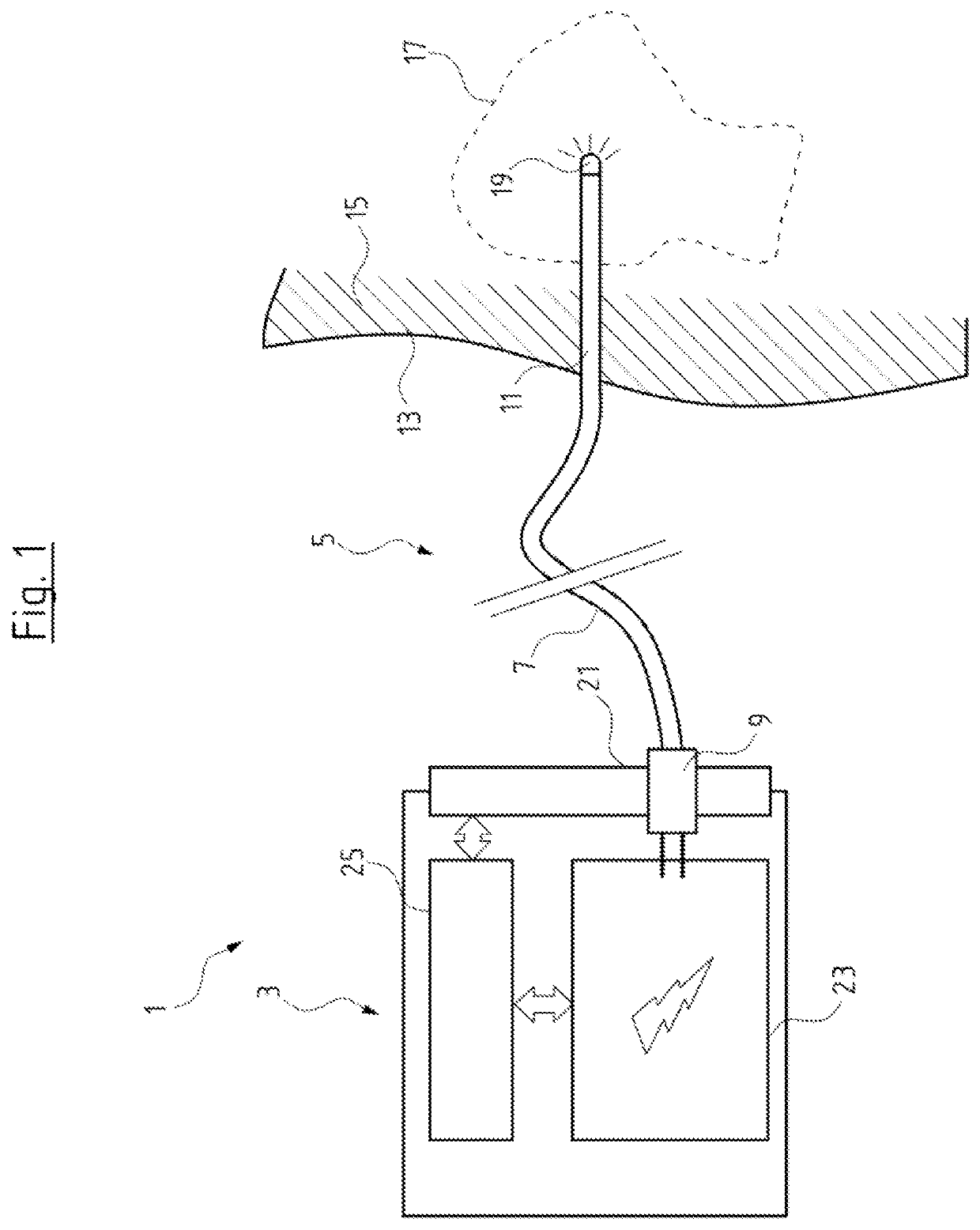
[0071]FIG. 1 shows a light applicator system 1 with a light applicator operation unit 3 and an exchangeable light applicator 5. The light applicator 5 consists essentially of a flexible cable section 7 which extends from a proximal-side plug 9 to a distal-side insertion section 11. The insertion section 11 in contrast to the cable section 7 is the section of the light applicator 5 which is envisaged to be pierced into organic tissue of a body 13. The light applicator 5 here is suitable for percutaneous PDT and is shown in PDT operation. The insertion section 11 here is configured as a rigid needle section which for example assisted by CD or ultrasound from the outside and with the distal tip is pierced through the skin 13 of a patient and underlying healthy tissue 15 into pathological body tissue 17, e.g. a malignant tumour.

[0072]At the distal tip, the insertion or needle section 11 comprises a distal-side LED 19 for in-situ generation of excitation light for the PDT. If for example...


PUM


Abstract

A light applicator (5) for examining and/or treating an organic body includes a minimal-invasive, rigid, semi-flexible or flexible insertion section (11) which extends along a longitudinal direction (L) and at its distal end includes an LED (19). The light applicator (5) includes a first electrical lead (61a) for the supply of electricity to the LED (19). The lead extends in the insertion section (11) in the longitudinal direction (L) and there has a cross-sectional area of at least 70% of the cross-sectional area of the light applicator (5). The light applicator (5) in the insertion section (11) is thermally insulated in the radial direction in a manner such that the radial thermal insulation reduces proximally.

Description

CROSS REFERENCE TO RELATED APPLICATIONS[0001]This application is a United States National Phase Application of International Application PCT / DE2020 / 200069, filed Aug. 13, 2020, and claims the benefit of priority under 35 U.S.C. § 119 of German Application 10 2019 212 199.3, filed Aug. 14, 2019, the entire contents of which are incorporated herein by reference.TECHNICAL FIELD[0002]The present disclosure relates to a light applicator for examining and / or treating an organic body, in particular for the photodynamic therapy (PPT) of pathological tissue.TECHNICAL BACKGROUND[0003]It is known to use endoscopes in order to make video recordings of the inside of a human or animal body for the purposes of medical diagnosis and / or therapy. Herein, one constantly strives to design the insertion section of the endoscopes as thinly a possible, so that one can inspect as small as possible cavities and that the tissue suffers as little as possible injury.[0004]However, endoscopes are not only used ...

Claims


Application Information

Patent Timeline
IPC IPC(8): A61N5/06
CPCA61N5/0601A61N5/062A61B2018/00095A61B1/012A61B1/0676A61B1/0684A61B1/12A61B1/00114A61B2018/00148A61B2018/1807A61B2018/00101A61N2005/0612A61B2018/2005A61N2005/005A61N2005/0651A61B2018/00005
Inventor WEBER, BERND CLAUSWIRTH, MANFRED
Owner RICHARD WOLF GMBH
Why Eureka
Try Eureka