Camshaft adjusting device

Active Publication Date: 2018-11-06
SCHAEFFLER TECH AG & CO KG
View PDF24 Cites 0 Cited by
  • Summary
  • Abstract
  • Description
  • Claims
  • Application Information

AI Technical Summary

Benefits of technology

The present invention provides a camshaft adjuster that can reliably and cost-effectively lock the rotor in position. The adjuster includes a band check valve that is pre-stressed to prevent fluid flow when not under pressure. When pressure is applied, the band reduces its size to unblock the fluid flow. The band check valve can be integrated into the valve pin or pre-stressed inwardly.

Problems solved by technology

One disadvantage of this approach is that the rotor can be locked only with multiple successively locking pins, which results in higher costs.

Method used


Image

  • Camshaft adjusting device
  • Camshaft adjusting device
  • Camshaft adjusting device

Examples


Embodiment Construction

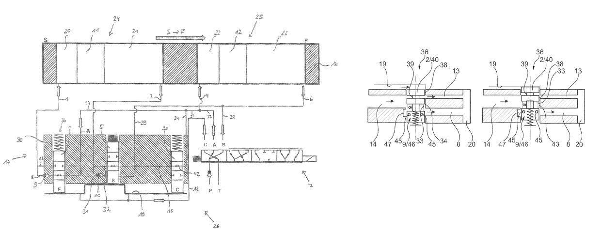
[0026]A camshaft adjusting device is apparent in FIG. 1, having a known basic construction with a schematically depicted vane cell adjuster as the basic component, which includes a stator 16 drivable by a crankshaft not depicted and a rotor 17 rotatably fixedly connectable to a camshaft also not depicted having multiple vanes 11 and 12 extending radially outwardly therefrom. In the upper development drawing, the vane cell adjuster is apparent, whereas a detail of rotor 17 having a center locking device 26 is apparent at the bottom left and a switching device in the form of a selector switch valve 7 for controlling the pressure medium flow is apparent at the bottom right. Selector switch valve 7 includes an A-port, B-port and C-port, to which pressure medium lines 18, 27 and 28 are fluidically attached. In addition, selector switch valve 7 is fluidically connected to a pressure medium reservoir T and to a pressure medium pump P which, during an actuation of the camshaft adjusting dev...


PUM


Abstract

A camshaft adjusting device, including a vane cell adjuster having a stator connectable to a crankshaft and a rotor, which is rotatably supported in the stator and connectable to a camshaft. Webs on the stator, divide an annular space between the stator and the rotor into pressure chambers, wherein the rotor has a rotor hub and vanes extending radially outward from the rotor hub, which vanes divide the pressure chambers into two groups of working chambers having a different acting direction, into each of which working chambers pressure medium flowing in or out in a pressure-medium circuit can be admitted, and a central locking device for locking the rotor in relation to the stator. The central locking device has two spring-loaded locking pins in an accommodating space, and lockable in a locking slot secured to the stator and lock in the locking slot when the rotor rotates from the direction of an “early” or “late” stop position into the locking position from different directions, wherein the locking pin forms a valve device together with the particular accommodating space, wherein the locking pin is a step pin.

Description

[0001]The present invention relates to a camshaft adjusting.[0002]Camshaft adjusting devices are generally used in valve trains of internal combustion engines in order to alter the valve opening and closing times, as a result of which the consumption values of the internal combustion engine and the operating behavior may generally be improved.BACKGROUND[0003]One specific embodiment of the camshaft adjusting device proven in practice includes a vane cell adjuster with a stator and a rotor, which delimit an annular space, which is subdivided by projections and vanes into multiple working chambers. The working chambers may be selectively acted upon by a pressure medium, which is fed in a pressure medium circuit via a pressure medium pump from a pressure medium reservoir into the working chambers on one side of the vanes of the rotor and is fed from the working chambers on the respective other side of the vanes back to the pressure medium reservoir. The working chambers, the volume of w...

Claims


Application Information

Patent Timeline
IPC IPC(8): F01L1/34F01L1/344
CPCF01L1/3442F01L2001/34453F01L2001/34466F01L2001/34463F01L2001/34459F01L2001/34476
InventorZSCHIESCHANG, TORSTENRAECKLEBE, STEFFEN
OwnerSCHAEFFLER TECH AG & CO KG