

Transporting apparatus with articulated conveying element
a technology of conveying element and transporting apparatus, which is applied in the direction of conveyor parts, non-mechanical conveyors, rollers, etc., can solve the problems of shortening the maintenance interval of the transport system, and achieve the effect of reducing the radii, occupying little space, and saving installation spa
- Summary
- Abstract
- Description
- Claims
- Application Information
AI Technical Summary
Benefits of technology
Problems solved by technology
Method used
Image

Examples
Embodiment Construction
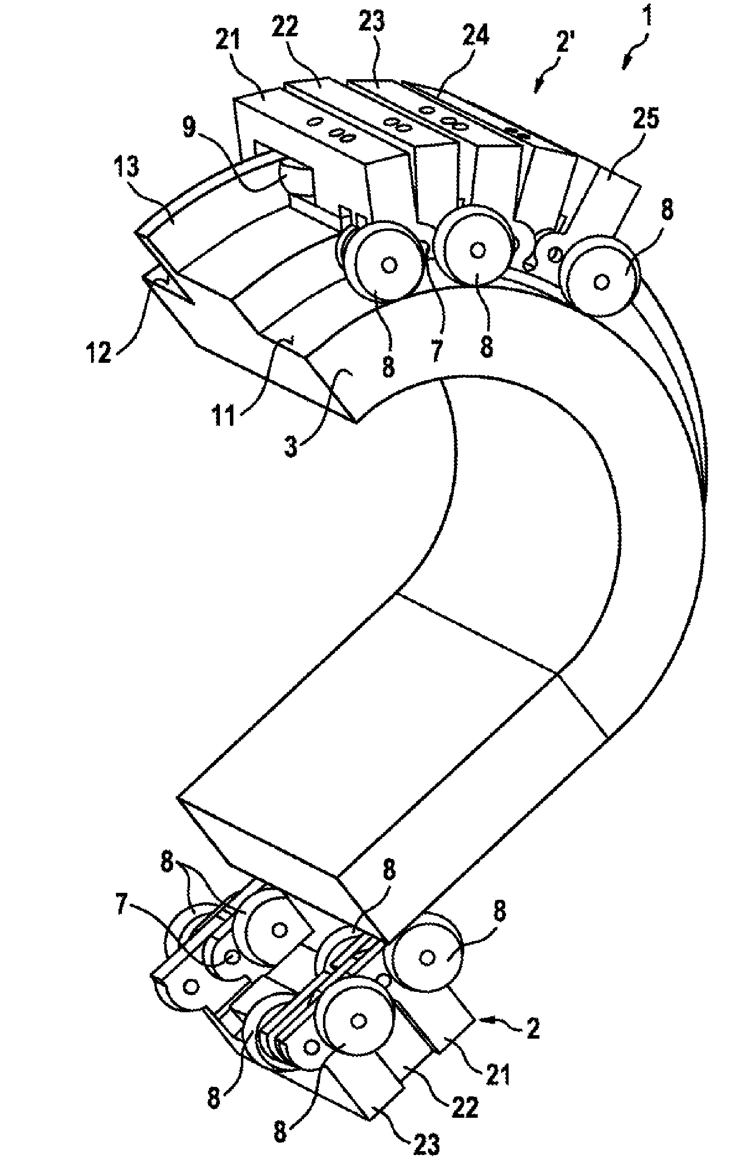
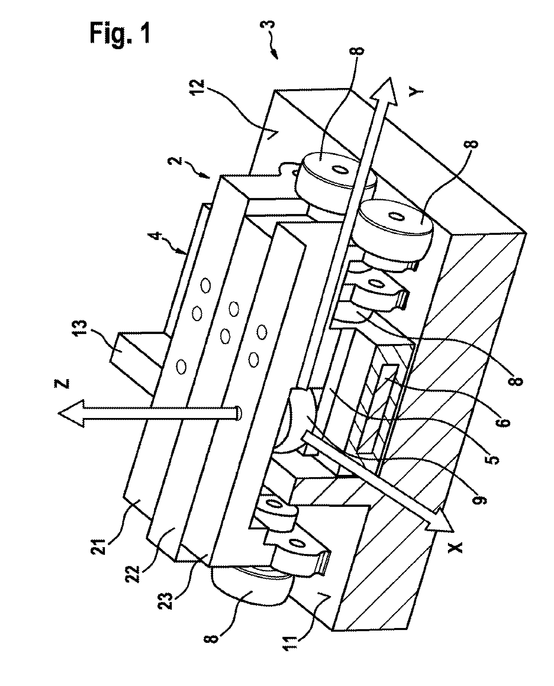
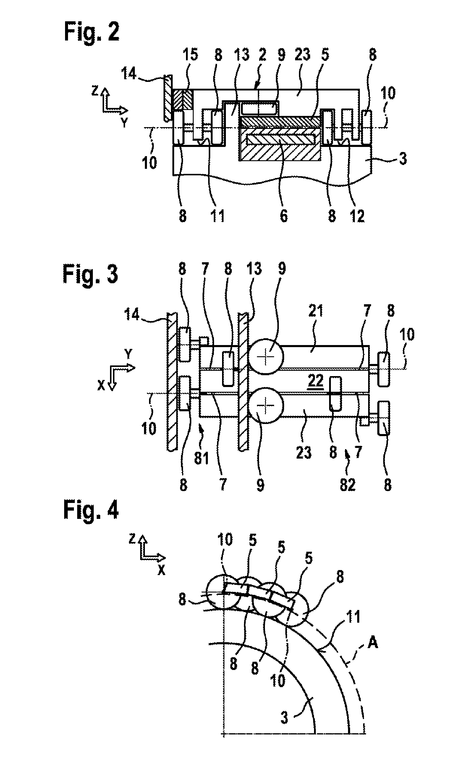
[0021]A transporting apparatus 1 according to a first preferred exemplary embodiment of the invention is described in detail below with reference to FIGS. 1 to 5.
[0022]As can be seen from FIG. 1, the transporting apparatus 1 comprises a conveying element as well as a running rail 3, which is only shown in part in FIG. 1 and is provided in a fixed and peripheral manner. The running rail 3 has a design with linear part regions as well as curved regions such that in total an oval-shaped section is produced. In addition, it is also possible to have other forms of running tracks, e.g. shaped in an angular manner, which are assembled from modular linear and curved elements. The running rail 3 comprises a first running track 11, a second running track 12 and a guide rail 13 which is arranged between the two running tracks. In addition, there is provided a linear motor driving device 4, which comprises a plurality of coils 6 which are arranged in the running rail 3 and permanent magnets 5 w...
PUM
 Abstract
Description
Claims
Application Information