Conveying device with articulated conveying element

a conveying element and conveying device technology, applied in the direction of non-mechanical conveyors, conveyors, transportation and packaging, etc., can solve the problems of iron reflux plate interruption, particularly disadvantageous in packaging technology applications, etc., and achieve the effect of reducing the radii of the curved region and small curve radii

Active Publication Date: 2015-06-16
SYNTEGON TECHNOLOGY GMBH
View PDF8 Cites 20 Cited by
  • Summary
  • Abstract
  • Description
  • Claims
  • Application Information

AI Technical Summary

Benefits of technology

[0003]The inventive conveying device for product conveyance has in contrast the advantage that said device, on the one hand, enables the reduction of the radii of the curved regions at a constant air gap between the arc-shaped primary parts and the permanent magnets and that, on the other hand, a common iron reflux plate is used. As a result, a targeted guidance of the magnetic flux can be provided. According to the invention, this is achieved by virtue of the fact that the conveying device comprises a plurality of individually movable conveying elements which each have at least one first sub-component and one second sub-component which are connected to one another in an articulated manner by means of a hinge. Thus, this design allows for smaller curve radii. In this case, each sub-component has at least one permanent magnet. The hinge between the sub-components is thereby arranged on a reflux plate such that the reflux plate is sub-divided into a first and a second plate part, each plate part being arranged on a sub-component of the conveying element. In so doing, the articulability of the conveying elements is maintained and the conveying elements comprise plate parts of the reflux plate connected to one another by means of hinges; thus enabling virtually a common reflux plate to be maintained during operation. As a result, the inventive reflux plate that is sub-divided in an articulated manner has approximately the same properties as a conventional, one-piece reflux plate.
[0005]In an embodiment that is as cost-effective and simple as possible, the hinge between the plate parts of the reflux plate is formed by means of a tooth system.
[0006]A particularly cost-effective production of a conveying element according to the invention is possible if the first and the second plate part have an identical geometric shape and if, in the assembled state, the second plate part is disposed so as to be rotated by 180° about a longitudinal axis of the conveying element. As a result, the number of non-variable parts can be increased and the costs of production and assembly can be greatly reduced.
[0008]In a particularly preferred manner, a clearance fit is present between the teeth of adjacent plate parts in the assembled state. In this way, a sufficient movement capability of the teeth for providing the articulated function is ensured; and, on the other hand, too great a play is not present which could lead to undesired noises during the operation of the conveying element.
[0010]Furthermore, the conveying element preferably comprises a second hinge which is disposed between frame components of the sub-components of the conveying element. In this way, an undesirable loading of the first hinge can be prevented in the region of the tooth system between the plate parts of the reflux plate.

Problems solved by technology

A disadvantage with this conveying device is however that an iron reflux plate has to be interrupted for design reasons due to the conveying elements which are constructed from individual sub-components that are connected to one another in an articulated manner.
This is particularly disadvantageous in applications in the field of packaging technology.

Method used


Image

  • Conveying device with articulated conveying element
  • Conveying device with articulated conveying element
  • Conveying device with articulated conveying element

Examples


Embodiment Construction

[0017]A conveying device 1 according to a preferred exemplary embodiment of the invention is described below in detail with reference to the FIGS. 1 to 4.

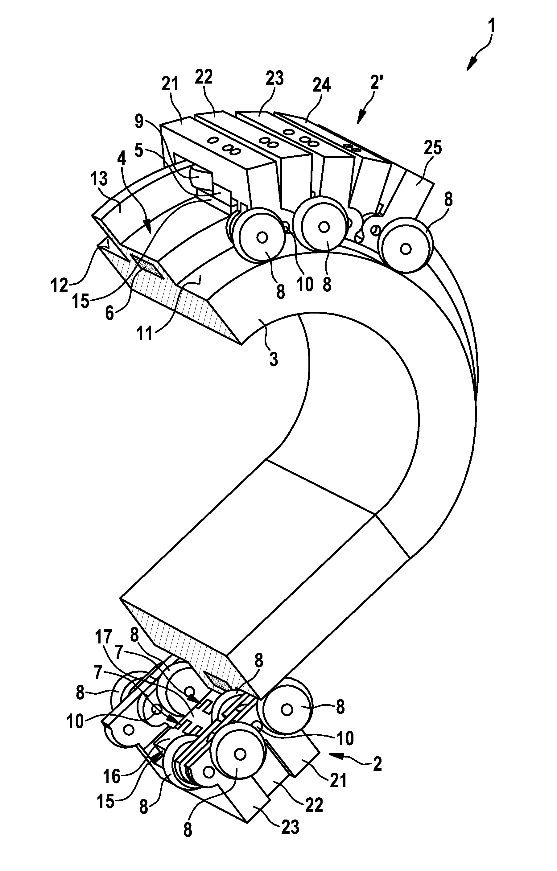
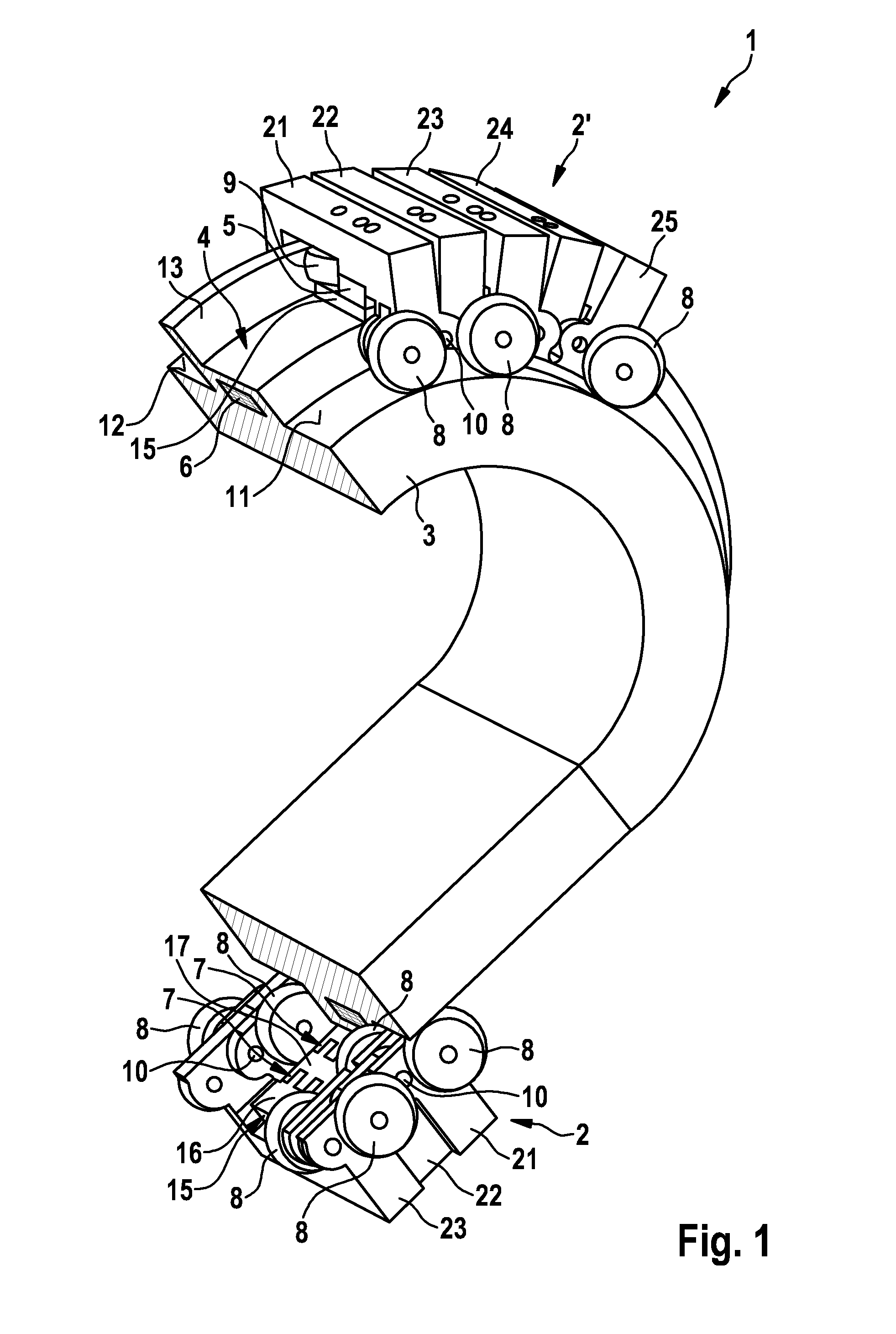
[0018]As can be seen in FIG. 1, the conveying device 1 comprises a plurality of conveying elements 2, 2′ as well as a stationary and circumferentially arranged guide rail 3, which is only partially depicted. The guide rail 3 has a design comprising linear partial regions as well as curved regions so that overall an oval-shaped track results. In addition, other forms of the track, e.g. angular, are possible, which are composed of modular linear and curved elements. The guide rail 3 comprises a first track 11, a second track 12 as well as a guide bar 13 located between the two tracks.

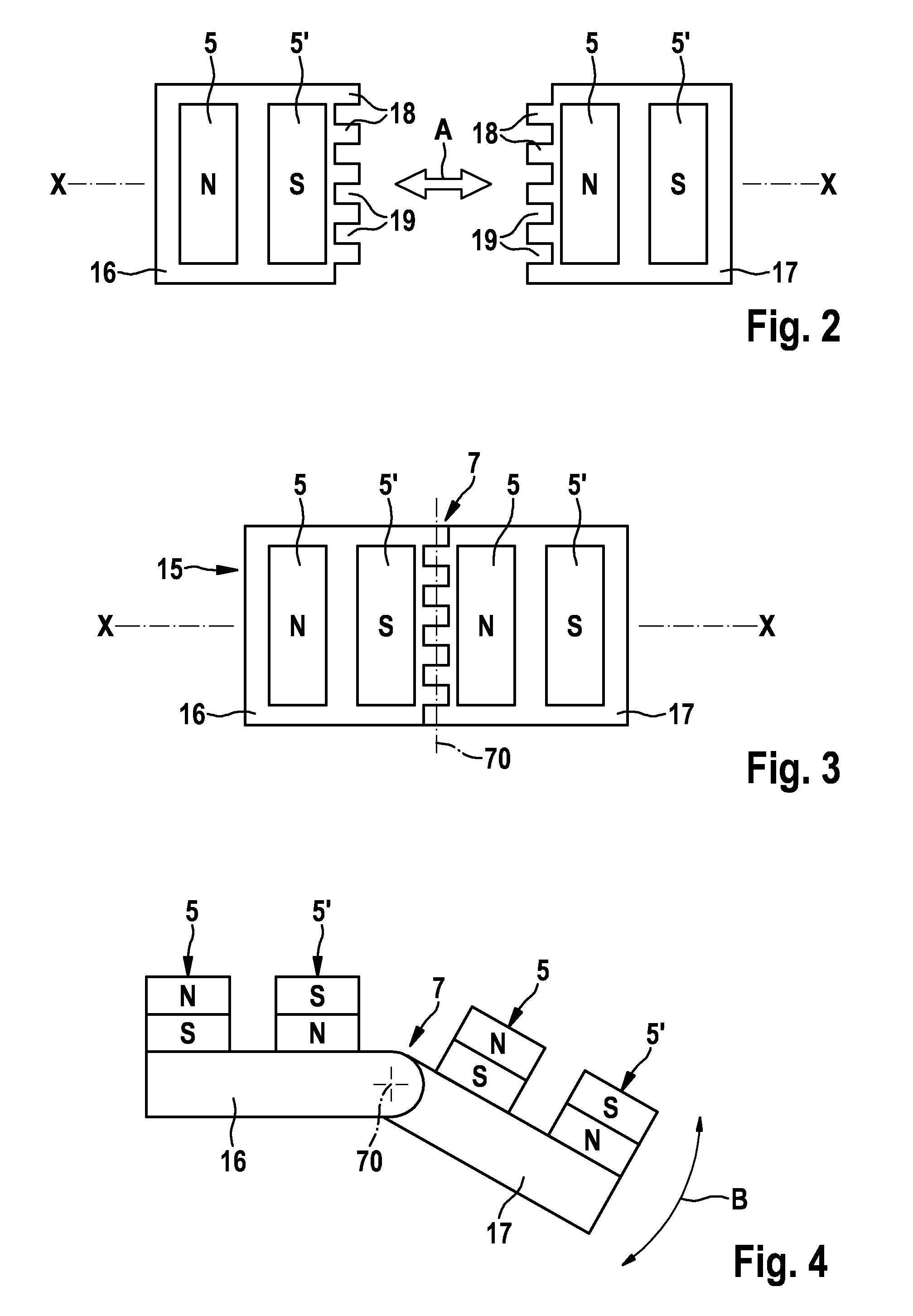
[0019]A linear motor drive device 4 is furthermore provided which comprises a plurality of coils 6 disposed in the guide rail as well as permanent magnets disposed on the conveying element 2. In this way, a conveying device comprising a plurality of conv...


PUM


Abstract

A conveying device for conveying a product, comprising a plurality of individually movable conveying elements (2, 2′) for conveying the products, a stationary, circumferentially arranged guide rail (3), which defines a running path for the conveying elements (2, 2′), and a linear motor drive device (4) for driving the conveying elements (2, 2′), said conveying elements (2, 2′) each having permanent magnets (5, 5′) which are actively connected to the coils (6) of the linear motor drive device (4), each conveying element (2, 2′) having at least one first sub-component (21) and one second sub-component (22) which are connected to one another in an articulated manner by means of a hinge (7), each sub-component (21, 22) having at least one permanent magnet (5, 5′), each conveying element (2, 2′) having a reflux plate (15), and the hinge (7) being arranged on the reflux plate (15) in such a way that the reflux plate (15) is sub-divided into a first plate part (16) and a second plate part (17), which are connected to one another via the hinge (7).

Description

BACKGROUND OF THE INVENTION[0001]The present invention relates to a conveying device comprising a plurality of articulated, individually movable conveying elements, in particular for conveying products for a feed of packaging machines.[0002]Conveyor systems for conveying products, in particular for use with packaging machines, are known from the prior art in various embodiments. The German patent specification DE 10 2010 027 925 A1 discloses, for example, a conveying device comprising an articulated conveying element, which can pass through very tight radii in a circumferential guide rail by the provision of hinges between individual sub-components of the conveying element. Wear and any slipping motion of the guide rollers are prevented here in the curved region. A disadvantage with this conveying device is however that an iron reflux plate has to be interrupted for design reasons due to the conveying elements which are constructed from individual sub-components that are connected t...

Claims


Application Information

Patent Timeline
Patent Type & Authority Patents(United States)
IPC IPC(8): B65G17/06B65G23/18B65G17/32B65G17/40B65G54/02
CPCB65G17/06B65G23/18B65G17/32B65G54/02B65G17/40
Inventor VAN DE LOECHT, HEINRICHREINISCH, MARTIN
Owner SYNTEGON TECHNOLOGY GMBH
Why Eureka
Try Eureka