Display panel and display panel manufacturing method

a technology for display panels and manufacturing methods, applied in the field of display panels, can solve the problems of deterioration in the properties of organic el elements, high instability of the material used for the structure of organic el laminates, and the inability to manufacture electrode systems, etc., to achieve yield optimization, improve manufacturing efficiency, and reduce the amount of protruding corners of rectangular frames

Active Publication Date: 2014-07-03
JOLED INC
View PDF11 Cites 23 Cited by
  • Summary
  • Abstract
  • Description
  • Claims
  • Application Information

AI Technical Summary

Benefits of technology

[0013]The display panel pertaining to one aspect of the present disclosure has a reinforced portion protruding outward from a corner portion of a rectangular frame, such that residual strain, produced during heating in the manufacturing process of the display panel, mainly occurs in regions outside the reinforced portion. The reinforced portion also includes a side face cut so as to be aligned with a side face of a corner portion of at least one of a first substrate and a second substrate. Thus, cutting is performed closer to the center of the display panel than a region where the residual strain occurs. In comparison to cutting inside the region where the residual strain occurs, this approach better prevents fracturing of the first and second substrates during the cutting process, thereby improving manufacturing efficiency (i.e., yield optimisation).
[0014]Accordingly, the reinforced portions protrude outward from the corner portions of the rectangular frame. However, given that the reinforced portions include a side face cut so as to be aligned with at least one side face of a corner portion of a first substrate and a corner portion of a second substrate, cutting is performed across the reinforced portions. As a result, the amount of protrusion from the corner portions of the rectangular frame is reduced, thereby satisfying the demand for reduction in the width of the frame.
[0015]As described above, the presence of the reinforced portions protruding outward from the corner portions of the rectangular frame enables fractures of the first and second substrates due to residual strain to be prevented at cutting time, and enables the radius of the corner portions to be reduced (i.e., provides corners closer to right angles) so as to respond to demand for reduction in the width of the frame.

Problems solved by technology

The material used for the organic EL laminate structure is typically unstable and highly active, prone to reacting with water and oxygen in the atmosphere.
These reactions with atmospheric water and oxygen are a cause of deterioration in the properties of the organic EL element.

Method used


Image

  • Display panel and display panel manufacturing method
  • Display panel and display panel manufacturing method
  • Display panel and display panel manufacturing method

Examples


embodiment 1

1. Configuration

(1) Overall Configuration

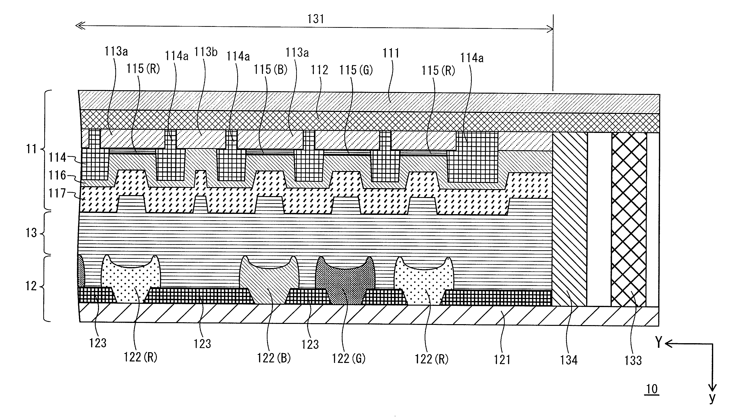
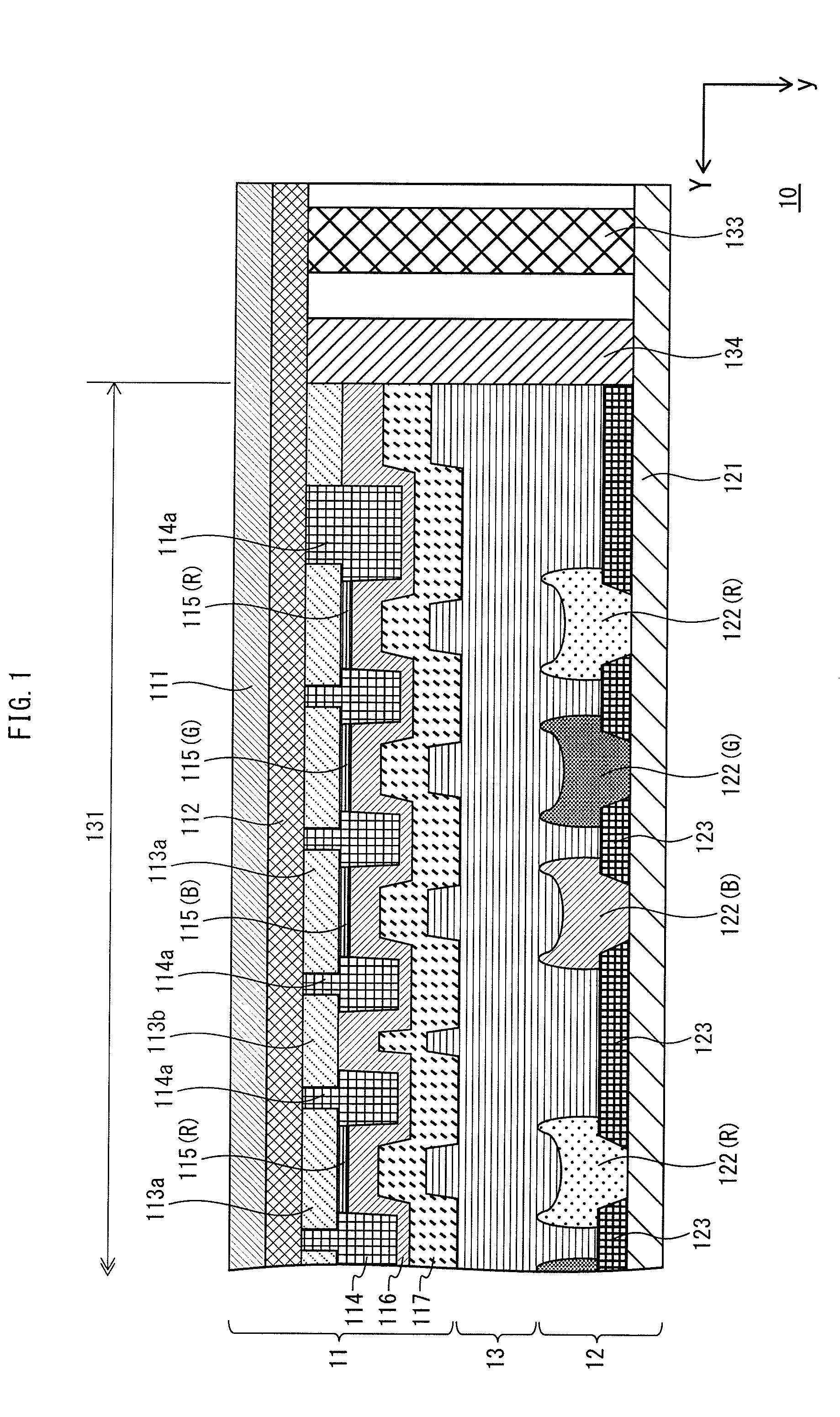
[0049]FIG. 1 is a partial cross-sectional diagram schematically illustrating key portions of a display panel 10 pertaining to Embodiment 1.

[0050]As shown, the display panel 10 includes an EL substrate 11 and a colour filter (hereinafter also CF) substrate 12, as well as a sealing resin layer 13 interposed between the EL substrate 11 and the CF substrate 12.

[0051]The sealing resin layer 13 is provided and applied in liquid form and then cured, with the aims of conjoining the EL substrate 11 and the CF substrate 12 and of protecting the EL substrate 11 from infiltration by water and gas from outside the display panel 10. However, the sealing resin layer 13 is not strictly necessary and may be omitted from the configuration.

[0052]Light exits the display panel 10 from the top or front. However, with respect to FIG. 1, light exits from the bottom as drawn.

(2) EL Substrate

[0053]The EL substrate 11 is made up of a substrate, an inter-layer insulatio...

embodiment 2

[0163]As shown in FIG. 13, Embodiment 1 describes cutting the EL substrate and the CF substrate to identical dimensions. That is, the cut face (i.e., side face) of the EL substrate and the cut face (i.e., side face) of the CF substrate are cut so as to match along the entire respective perimeters thereof.

[0164]However, the EL substrate and the CF substrate may differ in terms of dimensions. Embodiment 2 describes an example of such a case (i.e., where the cut faces do not match).

1. Mono-Panel Method

[0165]FIGS. 16A and 16B illustrate an example pertaining to Embodiment 2 in which the display panel has substrates of different dimensions. FIG. 16A is a plan view of the display panel and FIG. 16B is a magnified perspective view of a corner of the intermediate panel.

(1) Overview

[0166]A display panel 300 has a display region 302 sealed by a sealing member 305 when an EL substrate 301 and a CF substrate 303 are joined to each other. As indicated by the dashed line in FIG. 16A, the sealing ...

example 1

(a) Example 1

[0225]As shown in FIG. 21A, reinforced portion 501 pertaining to Example 1 is arranged at the outside of a corner portion 505 of rectangular frame 503 so as to be continuous with the corner portion 505. The reinforced portion 501 is round as seen in the plan view, and the interior thereof is not filled by the frit paste.

[0226]The reinforced portion 501 is formed so as to bridge edge portion 507 and edge portion 509, which meet at corner portion 505 of the rectangular frame 503. In other words, the reinforced portion 501 is formed so as to extend from one edge portion of the corner portion 505 (e.g., edge portion 507) and curve in a circle before continuing to the other edge portion (e.g., edge portion 509).

[0227]According to this configuration, the frit paste is applied with a single stroke, thus enabling more efficient frit paste application.


PUM


Abstract

A display panel comprises a first substrate, a second substrate arranged opposite the first substrate, electroluminescence elements disposed between the first substrate and the second substrate, and a sealing member provided between the first substrate and the second substrate, sealing the electroluminescence elements. The sealing member includes a rectangular frame formed along a perimeter of the electroluminescence elements and a reinforced portion protruding outward from a corner portion of the rectangular frame, the reinforced portion includes a first side face cut so as to be flush with at least one corner side face of the first substrate, and a second side face cut so as to be flush with a corresponding corner side face of the second substrate.

Description

TECHNICAL FIELD[0001]The present disclosure pertains to a display panel and a manufacturing method therefor, where a display region provided between two opposing substrates is sealed by a sealing member that surrounds the display region while also being provided between the substrates.BACKGROUND ART[0002]An organic electroluminescence (hereinafter, EL) element is a type of self-illuminating element and, as such, requires no backlight while providing a wide viewing angle, is easily applicable to thinning and power consumption reduction, and has a high response speed, among other merits. An organic electroluminescence panel (hereinafter, EL panel) in which such EL elements are arranged has come to attention as a next-generation display panel serving as a replacement for liquid crystal devices.[0003]Typically, an organic EL element has an organic EL laminate structure in which a an organic material layer that incudes a lower electrode and a light-emitting layer is sequentially layered ...

Claims


Application Information

Patent Timeline
Patent Type & Authority Applications(United States)
IPC IPC(8): H05B33/04H05B33/10
CPCH05B33/10H05B33/04H10K50/8426
Inventor MASUDA, HIROYUKI
Owner JOLED INC
Why Eureka
Try Eureka