Wind turbine device

a wind turbine and blade technology, applied in the direction of electric generator control, renewable energy generation, greenhouse gas reduction, etc., can solve the problems of excessive vibration during operation, limit the noise during operation, and the tendency to “run away”

Inactive Publication Date: 2008-04-22
BECKER WILLIAM S
View PDF51 Cites 75 Cited by
  • Summary
  • Abstract
  • Description
  • Claims
  • Application Information

AI Technical Summary

Benefits of technology

[0009]The present invention comprises in one form a hybrid wind turbine formed of both an inner helical screw-type blade design, with the individual helical blades formed of flexible segmented vane members operable as an air valve to allow air to pass between them when in their leeward (non-wind-gathering) position relative to the wind so as to reduce blade drag, and at least a pair of outer generally straight airfoil blades, which are of greater overall length than the inner helical blades. The entire hybrid blade combination is mounted for rotation within a protective cage structure to prevent unwanted entry of humans, birds and other objects in the blade path, and to help with secure, low vibration mounting, safety and insurability for urban settings.
[0010]The inner segmented helical screw-type S blades permit early start up of the hybrid turbine at low wind speeds. They also act as wind brakes at unduly high wind speeds to prevent runaway conditions. The outer airfoil blades enable the hybrid wind turbine to achieve high rotational speeds and resultant high energy production efficiencies at upper wind speeds. Together the helical and airfoil blades help maximize harvesting of wind energy. The present hybrid wind turbine operates with minimal noise and vibration, particularly since the segmented helical vane members operate at a rotational (varying torque) rate that does not exceed the speed of the wind by more than three and a half times and with a varying profile that always presents generally the same overall blade area to the wind. (This is in distinct contrast to standard “non-twisted”“S” rotors which, in essence, offer a alternating high- or wide- and then a low- or narrow-profile to the wind as they rotate.) This acts to substantially eliminate the “banging” noise and harmful action, especially in the support bearings, as found in many non-helical, non-twisted prior art Savonius-type turbine blades. The segmented helical screw blades, formed into two helical half wing blades, can be selectively formed with different numbers, and hence widths, of elongated vane segments, and with different spacing between such vane segments, depending upon the operational height at which the hybrid wind turbine will be mounted, and also upon the average annual wind speed available at that operational height. Additionally, both the cross-sectional shape of the outer airfoils, and their operational distance from the inner helical blades, can be altered for the same reasons. The inner helical blades can be alternatively formed as generally smooth-walled blades, i. e., formed via an edge-abutting or slightly overlapping series of flat panel segments but that in either case do not have edge separation during rotational operation.

Problems solved by technology

Each of those various Savonius-type blade designs have inherent limitations, including the limitation of noise during operation, excessive vibration during operation, a tendency to “run away” during elevated wind speed operations and often excessive drag created during rotation of the leeward or non-wind-gathering portion of the blade's movement.
However, these Darrieus-type designs also have inherent deficiencies, including that only the middle one-third of their blade length (at least for curved Darrieus blade versions) efficiently creates power; that the farther the distance from a curved blade to its axis of rotation, the greater the likelihood, especially in large scale power generation units, of a Darrieus type unit going into harmonic vibration and self-destructing; that all such Darrieus-blade type units are not self-starting, but need assistance in starting; and that in many wind conditions they can, on a periodic basis, use up more energy than they actually produce.
Without proper controls and / or mechanical braking systems, Darrieus type units (like Savonius units) have been known to “run away” during elevated wind speed conditions.
Yet in U.S. Pat. No. 3,918,839, significant difficulties arose relative to the operational, i. e., rotational, stability of the unit at high wind speeds.
In Tanzawa, the addition of a Savonius bucket rotor to start the Darrieus rotor resulted in a reduction in the total turbine power and high braking torque at higher rotational rates.
There were also the above-noted inherent problems present in all separate Darrieus and Savonius-type blade systems.
Most available wind turbine designs have problems of excessive noise and vibration, often self-destruct in high wind conditions, some require separate start-up, braking or stopping mechanisms, and many are not considered safe, readily insurable or building-code permitted, at least not for use in congested urban settings.

Method used


Image

  • Wind turbine device
  • Wind turbine device
  • Wind turbine device

Examples


Embodiment Construction

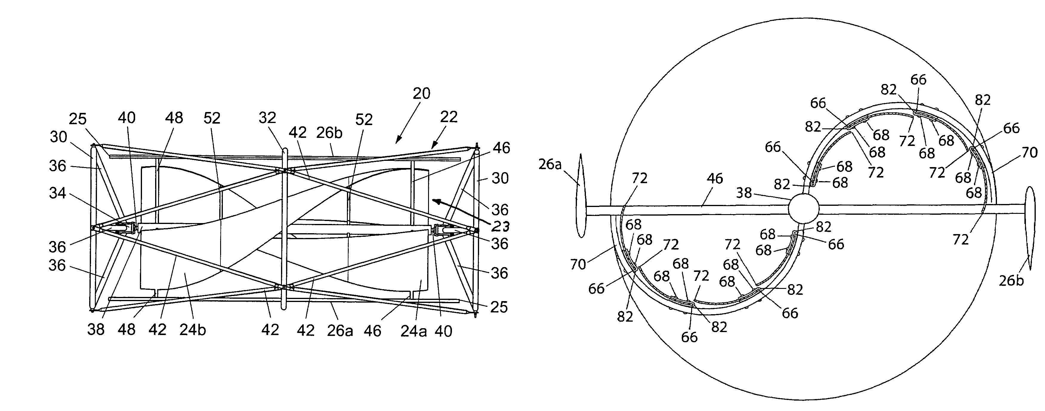
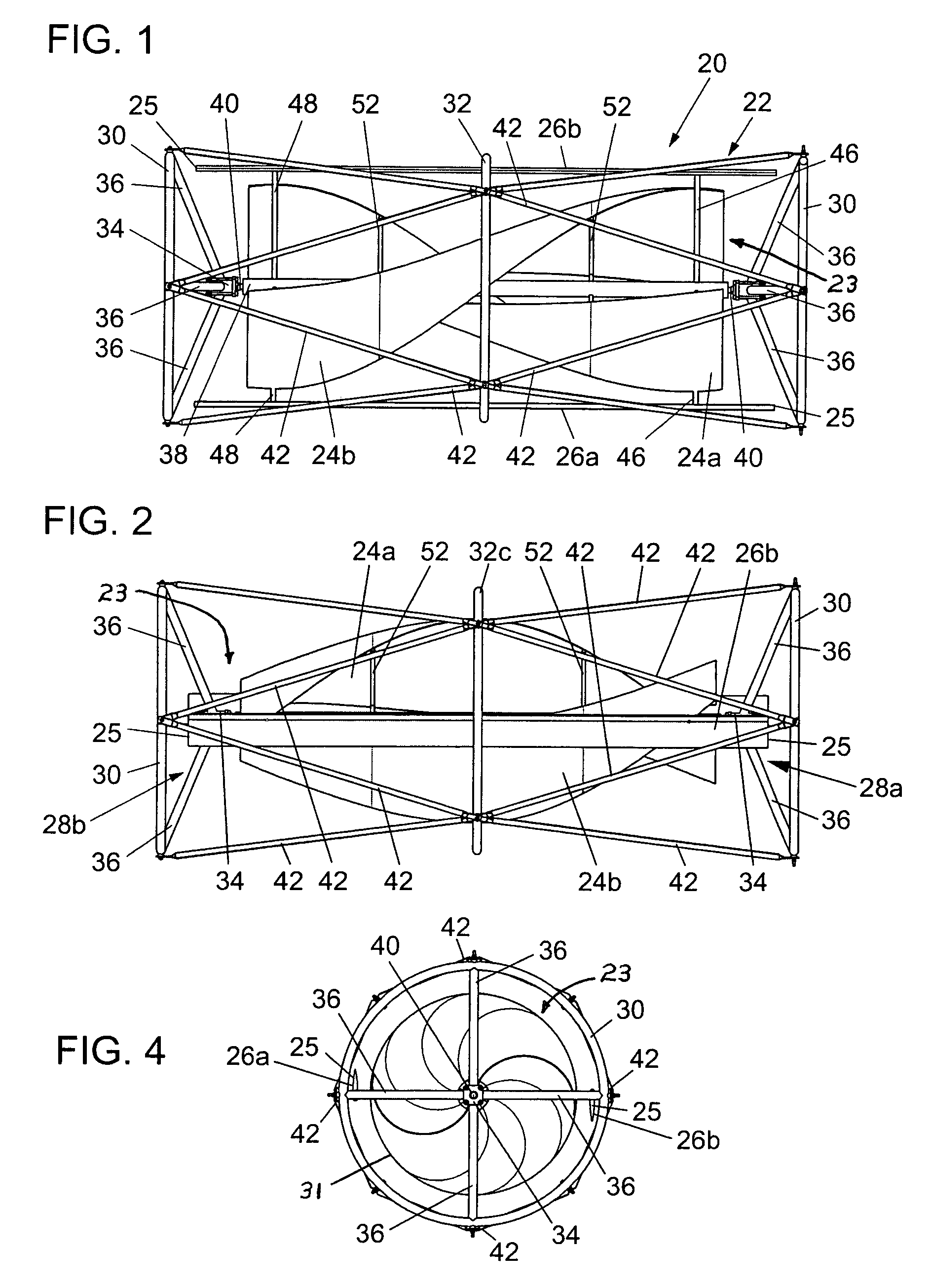
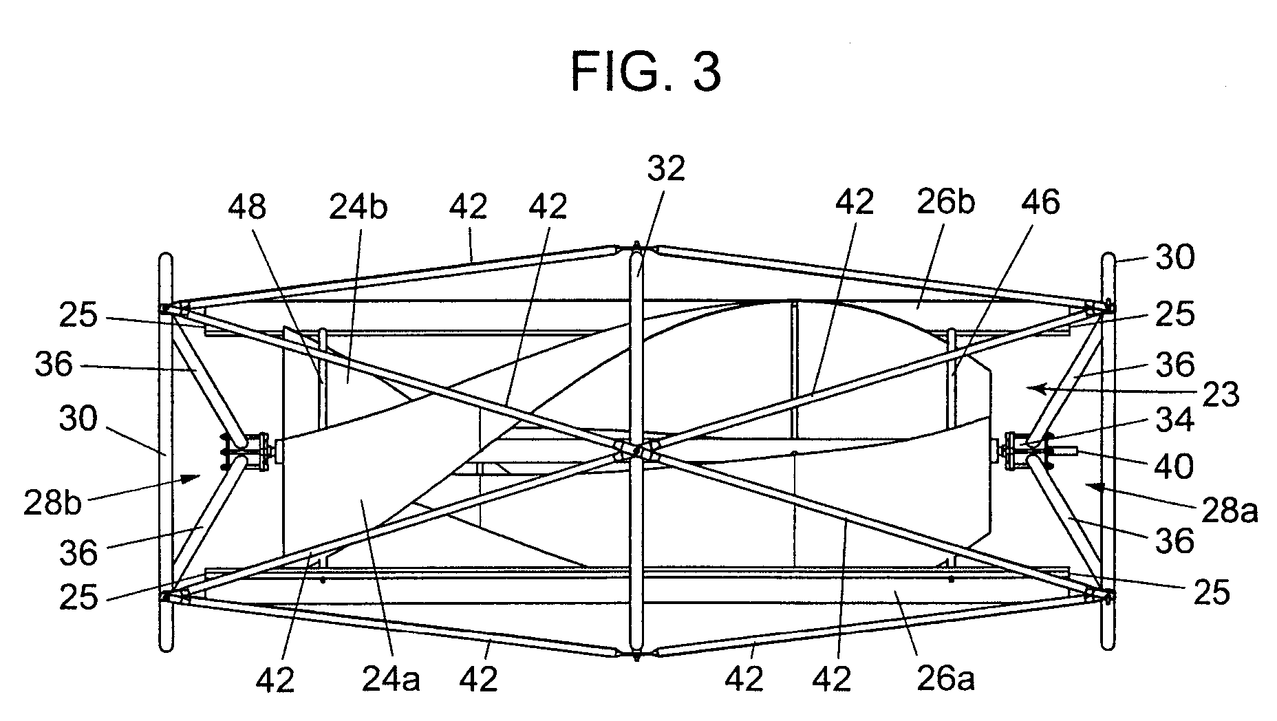
[0033]Having reference to the drawings, wherein like reference numerals indicate corresponding elements, there is shown in FIGS. 1 through 5 an illustration of a hybrid wind turbine device forming one embodiment of the present invention, namely a non-segmented blade version, as generally denoted by reference numeral 20. Hybrid turbine 20 includes an outer protective safety frame or cage generally denoted by reference number 22, and a combination turbine blade assembly 23 comprising a pair of non-segmented (generally smooth-walled) helically twisted inner turbine blades, namely helical half wing blades 24a, 24b, and a pair of diametrically opposed outer airfoil blades 26a, 26b. Each of the helically twisted inner turbine blades and the outer airfoil blades cooperates in wind conditions to drive the operation of the other type blade. Further, each of the helically twisted inner turbine blades and the outer airfoil blades cooperates to form an inherent structural geometry which guards ...


PUM


Abstract

A hybrid blade wind turbine device formed of at least a pair of straight outer airfoil blades, and a pair of inner helical wing blades, as supported for rotation within a safety protective cage structure, which wind turbine can be mounted in the vertical, horizontal, or other aligned operational positions. The inner helical half wing blades, being preferably somewhat shorter than the length of the outer airfoil blades, act to “regularize” the swirling wind regime flowing through the hybrid wind turbine, so as to maximize the efficiency of the outer airfoil blades. The helical half wing blades can be formed of individual segmented vane segments to provide improved operational capabilities for the overall hybrid wind turbine. To best harness annualized available wind conditions, the hybrid wind turbine can be customized, through modification of the number of vane segments, the selection of the specific shape of the outer airfoil blades, and the specific operational positioning of the outer airfoil blades. Alternatively, the helical half wing blades can be formed as generally smooth-walled blades.

Description

I. RELATED PATENT APPLICATION[0001]This patent application is a divisional of prior U.S. patent application, Ser. No. 10 / 629,370, filed Jul. 29, 2003, now U.S. Pat. No. 7,132,760.II. FIELD OF THE INVENTION[0002]This invention relates to wind turbine devices, and more particularly to a universal-axis wind turbine device having a combination of multiple blade designs and a surrounding safety cage structure.III. BACKGROUND OF THE INVENTION[0003]Various known designs of wind turbine structures include the common propeller blade type turbine, the so-called Darrieus blade type turbine, and the so-called Savonius blade type turbine.[0004]Several Savonius or “S”-rotor blade designs are known, including those typified in Canadian Patent No. 1,236,030, EPO Publication No. 0040193 B1, French No. 961,999, German No. 187865, Japanese Publication No. 60-090992, Swedish No. 65,940, WIPO No. WO / 99 / 04164, and U.S. Pat. Nos. 1,697,574 and 4,293,274. Each of those various Savonius-type blade designs h...

Claims


Application Information

Patent Timeline
Patent Type & Authority Patents(United States)
IPC IPC(8): F03D9/00H02P9/04
CPCF03D3/02F03D3/062F03D9/021Y02E10/74F05B2240/214F05B2240/40F05B2250/25F05B2240/213F03D9/11F03D9/25F03D13/20Y02E70/30
Inventor BECKER, WILLIAM S.
Owner BECKER WILLIAM S
Why Eureka
Try Eureka