Multiplier extension arrangement

a multi-purpose, extension arrangement technology, applied in the field of multi-purpose extension arrangement, can solve the problems that the jaws would likely not be able to tolerate such pinching or squeeze effect, and achieve the effect of shortening the distal advance capacity, facilitating the camming of the link, and increasing the combined overall length

Inactive Publication Date: 2006-11-28
MICROLINE SURGICAL INC
View PDF21 Cites 71 Cited by
  • Summary
  • Abstract
  • Description
  • Claims
  • Application Information

AI Technical Summary

Benefits of technology

[0020]Rotational movement of the first link about its respective horizontal guide pin thus effects a rotational movement of the second link member about its respective horizontal guide pin. Rotational movement of the second link member about it horizontal guide pin in the horizontal cam slot thus effects rotational movement of the third link member about its respective horizontal guide pin within the horizontal cam slot. Rotational movement of the third link member about its horizontal guide pin effects motion of the fourth link member about its respective horizontal guide pin situated in the horizontal cam slot. The angular displacement of each of the respective link members and their cammed action within the horizontal cam slot thus effects a longitudinal displacement of the distalmost or fourth link member which, being attached to the proximal end of the distal multiplier arm, effects longitudinal distal displacement thereof. Thus the zig-zag orientation of the connected links are rotated to a straighter alignment to effect to greater overall length of those links, thus effecting the greater length of travel of the distal push rod.
[0021]Thus a first distal displacement of the proximal multiplier arm effects a greater longitudinal displacement of the distal multiplier arm (than the dital displacement of the proximal multiplier arm) which thereby effects a greater longitudinal displacement of the push rod supported under the channel and thus effects greater displacement of the staples being pushed by the distalmost end of pushrod.
[0022]In the further embodiment of the present invention, a spring may be arranged between the distalmost end of the distal multiplier arm and a portion of the channel. This spring is arranged to provide assistance to the initiation of motion of the distalmost multiplier arm and hence the pushrod, thus helping in its efficiency.
[0025]The invention thus comprises an elongated medical clip applying device having a handle grip assembly on a proximal end thereof and an elongated channel with a pair of squeezable jaws on a distal end thereof, including a push rod arrangement having a distal end and a proximal end, yhe push rod arrangement utilized for advancing a plurality of clips in a sequential manner between said jaws. The push rod including: a multiplier extender arrangement to increase the distance of travel of the distal end of the push rod arrangement a multiple of the distance of travel of the proximal end of the push rod arrangement. The multiplier extender arrangement may comprise a plurality of connected links cammed between a pair of elongated parallel plates to cam the movement of the links during movement of the proximal end of the push rod arrangement. The elongated plates may comprise a first plate and a second plate spaced parallel and apart from one another by a spacer arrangement, the elongated plates having a longitudinal axis. The first plate may have a cam slot therein arranged at an acute angle with respect to the longitudinal axis of the elongated plates. The second plate may have a horizontal cam slot therein arranged in parallel with the longitudinal axis of the elongated plates. Each of th3e links may have a horizontal guide pin extending therefrom, each of the guide pins being in cammed engagement with the horizontal cam slot. A first of the links may have a diagonal guide pin extending therefrom. The diagonal guide pine may extend into the diagonal slot in the first plate. The multiplier extender arrangement has a proximal multiplier arm in contact with the proximal pusher rod, the multiplier extender arrangement having a distal multiplier arm in contact with the distal pusher rod.
[0026]The invention also comprises a method of extending the distance of travel of the distal end of a pushed movable component on a distal end of a frame of a medical device relative to the distance of travel of an input component on a proximal end of the frame, The method may comprise the steps of: connecting a multiplier extender arrangement between the pushed movable component and the input component on the frame of the medical device; arranging a plurality of connected articulated links in the multiplier extender arrangement; pushing the plurality of connected articulated links in a distal direction a first distance by the input component as the links are in a zig-zag orientation; pushing the pushed movable component a second distance, which second distance is greater than the first distance; straightening out the zig-zag orientation of the links as they are moved distally in the extender arrangement; camming the links in an arrangement of slots in a pair of opposed elongated, parallel plates to effect an angular reorientation of the links as they are moved distally to increase their combined overall length; arranging a handle grip assembly to replace a first push rod arrangement thereon having a shorter distal advance capacity; arranging a guide pin in each of the links; and mating the pins in the slots to facilitate said camming of the links with respect to the plates.
[0027]The invention also comprises a method of extending the reachable output length of a device where the input length of the device is limited, comprising: moving a first elongated input rod longitudinally a first distance along a longitudinal axis thereof from an input component on a frame of the device and into a multiplier arrangement; moving and output rod longitudinally a second distance along a longitudinal axis thereof from the multiplier arrangement to push a movable component of the device; connecting a multiplier extender arrangement between the pushed movable component and the input component on the frame of the device; arranging a plurality of connected articulated links in the multiplier extender arrangement; pushing the plurality of connected articulated links in a distal direction a first distance by said input component as the links are in a zigzag orientation; pushing the pushed movable component a second distance, which second distance is greater than the first distance; straightening out the zig-zag orientation of the links as they are moved distally in the extender arrangement; camming the links in an arrangement of slots in a pair of opposed elongated, parallel plates to effect an angular re-orientation of the links as they are moved distally to increase their combined overall length to extend the reach of the device.

Problems solved by technology

Should it be desired to utilize a longer legged clip to be pinched within the jaws of that crimping device, longer legged staples would jam such a mechanism and the jaws unfortunately would likely not be able to tolerate such a pinching or squeezing effect.

Method used


Image

  • Multiplier extension arrangement
  • Multiplier extension arrangement
  • Multiplier extension arrangement

Examples


Embodiment Construction

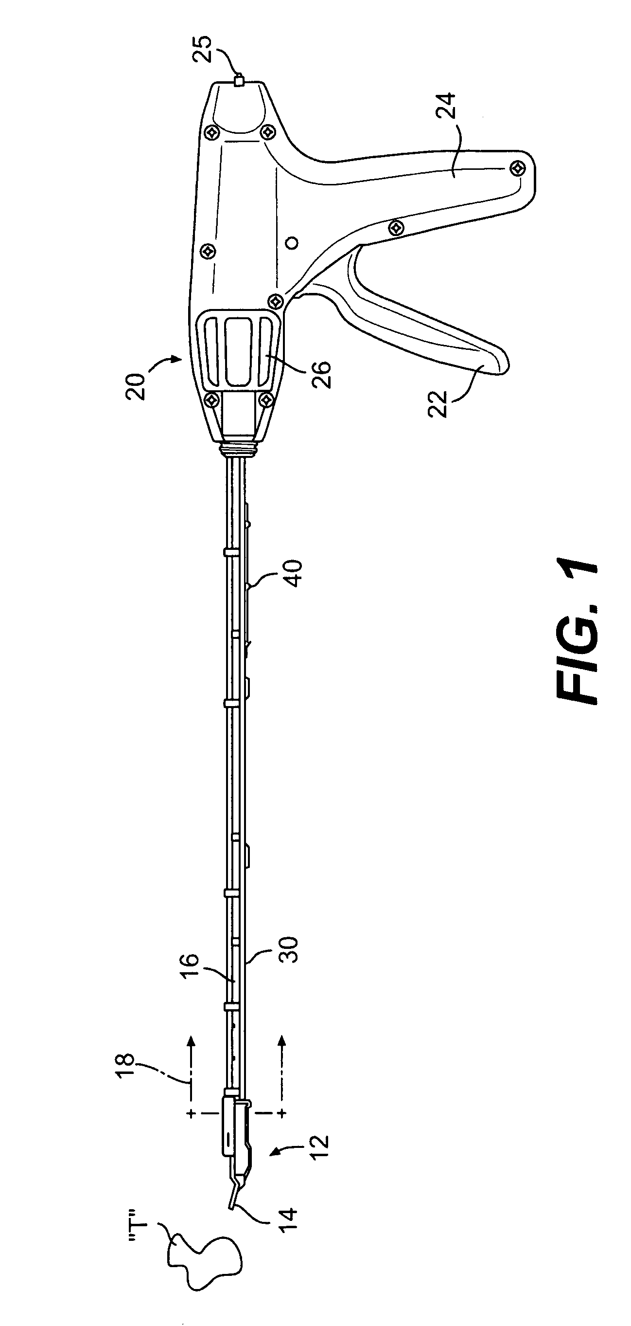
[0038]Referring now to the drawings in detail, and particularly to FIG. 1, there is shown the present invention which comprises a hand manipulable clip applying device 10 for applying medical tissue pinching clips to mammalian tissue “T”. The clip applying device 10 has a patient engaging distalmost end 12 with a pair of squeezable jaws 14 arranged on the distal end of an elongated channel or frame 16. The elongated channel 16 is normally surrounded by an elongated tubular barrel-like enclosure 18, which elongated tube 18 and elongated channel 16 are secured at their respective proximal most ends to the distal end of a pistol-like handle grip assembly 20. The handle grip assembly 20 includes an arcuately moveable, squeezable trigger 22. By squeezing the trigger 22 towards a housing portion 24 of the handle grip assembly 20, a clip (not shown for clarity) is advanced through the elongated channel 16 and between the jaws 14 distal of an elongated ladder-like clip supply cartridge (not...


PUM


Abstract

An elongated medical clip applying device having a handle grip assembly on a proximal end thereof and an elongated channel with a pair of squeezable jaws on a distal end thereof. A push rod arrangement is included having a distal end and a proximal end. The push rod arrangement is utilized for advancing a plurality of clips in a sequential manner between the jaws. The push rod includes a multiplier extender arrangement to increase the distance of travel of the distal end of the push rod arrangement a multiple of the distance of travel of the proximal or input end of the push rod arrangement.

Description

[0001]This application is a continuation-in-part application of U.S. patent application Ser. No. 10 / 158,726 filed 30 May 2002 now U.S. Pat. No. 6,911,033 entitled “Medical Clip Applying Device” which is a continuation-in-part of U.S. patent application Ser. No. 10 / 085,737 entitled “Medical Clip Applier Safety Arrangement” filed 28 Feb. 2002 which issued as U.S. Pat. No. 6,840,945, which is a continuation-in-part application of U.S. patent application Ser. No. 09 / 934,378 entitled “Safety Locking Mechanism for a Medical Clip Device” filed 21 Aug. 2001, which issued as U.S. Pat. No. 6,569,171, which is a continuation-in-part of U.S. patent application Ser. No. 09 / 795,808 entitled “Release Mechanism for Grasping Device” filed 28 Feb. 2001 which issued as U.S. Pat. No. 6,620,184, all of which are incorporated herein by reference, in their entirety.BACKGROUND OF THE INVENTION[0002]1. Field of the Invention[0003]This invention relates to a plurality of articulable links to extend the capab...

Claims


Application Information

Patent Timeline
Patent Type & Authority Patents(United States)
IPC IPC(8): A61B17/10A61B17/128A61B17/28
CPCA61B17/1285A61B2017/2919
Inventor MANETAKIS, EMMANUEL
Owner MICROLINE SURGICAL INC
Why Eureka
Try Eureka