Ultrasonic transducer, ultrasonic sensor, method of manufacturing ultrasonic transducer, and method of manufacturing ultrasonic sensor

a technology of ultrasonic transducers and sensors, applied in the direction of generators/motors, mechanical vibration separation, instruments, etc., can solve the problems of low ultrasonic wave sound pressure, low reception sensitivity, and low displacement of the bottom, so as to reduce manufacturing time and labor. , the effect of improving manufacturing efficiency

Active Publication Date: 2011-05-19
SEIKO EPSON CORP
View PDF3 Cites 75 Cited by
  • Summary
  • Abstract
  • Description
  • Claims
  • Application Information

AI Technical Summary

Benefits of technology

[0013]Therefore, according to the ultrasonic transducer of the aspect of the invention, the contraction amount of the piezoelectric member can be made larger, and the displacement amount of the bottom of the concave groove section with respect to the contraction amount of the piezoelectric member can also be made larger compared to the configuration of the related art in which one entire surface of the piezoelectric member is made to have close contact with the diaphragm, and therefore, it is possible to output the ultrasonic wave with higher sound pressure.
[0033]According to this aspect of the invention, the diaphragm stacking step and the second diaphragm stacking step are the same step, and the film for forming the diaphragms is formed at a time with the same process. Further, the concave groove forming step (step (b)) and the sacrifice layer embedding step (step (c)) are performed only on the ultrasonic transducer, and then the piezoelectric member forming step (step (d)) and the second piezoelectric member forming step (step (j)) are performed in the same step. Thus, it is possible to form the piezoelectric member of the ultrasonic transducer and the second piezoelectric member of the second ultrasonic transducer at a time. Further, by performing the support member forming step (step (g)) and the second support member forming step (step (k)) at the same step after removing the sacrifice layer of the ultrasonic transducer, the support member and the second support member are formed at a time. Thus, the significant reduction in the manufacturing time and the labor can be achieved, and the manufacturing efficiency can be improved compared to the manufacturing method of separately manufacturing the ultrasonic transducer and the second ultrasonic transducer.

Problems solved by technology

Therefore, there arises a problem that the sound pressure of the ultrasonic wave is low.
However, in the reception of the ultrasonic wave, since the diaphragm and the piezoelectric member do not have close contact with each other, the reception sensitivity is degraded.
Further, in the case in which the deflection is caused in the piezoelectric member, since the wall portion of the concave groove section is pulled toward the inside thereof after correcting the deflection of the piezoelectric member when the piezoelectric member is contracted, the amount of displacement of the bottom of the concave groove section is reduced as much as the correction of the deflection of the piezoelectric member, and thus the ultrasonic wave output therefrom becomes also weak.

Method used


Image

  • Ultrasonic transducer, ultrasonic sensor, method of manufacturing ultrasonic transducer, and method of manufacturing ultrasonic sensor
  • Ultrasonic transducer, ultrasonic sensor, method of manufacturing ultrasonic transducer, and method of manufacturing ultrasonic sensor
  • Ultrasonic transducer, ultrasonic sensor, method of manufacturing ultrasonic transducer, and method of manufacturing ultrasonic sensor

Examples


first embodiment

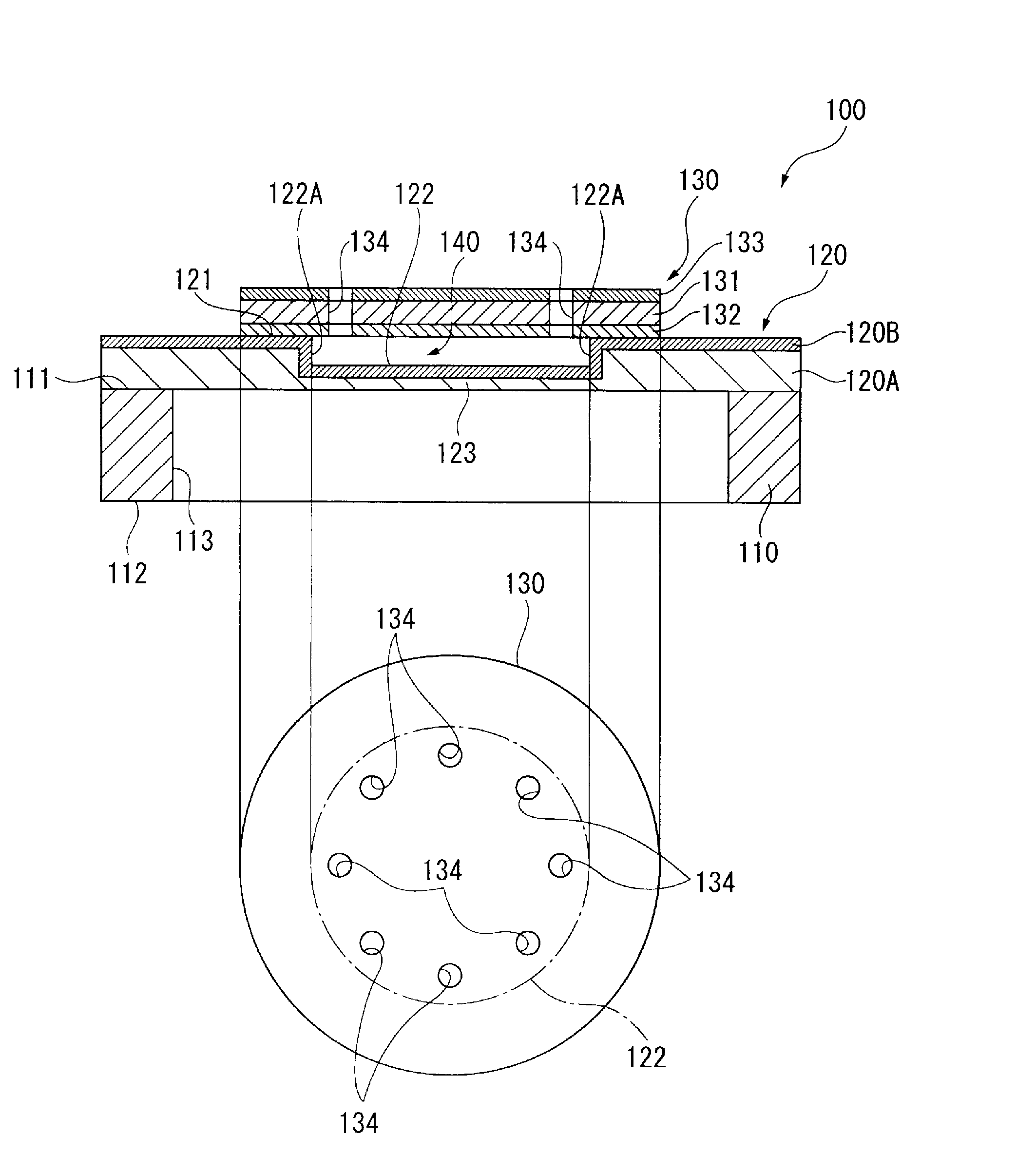
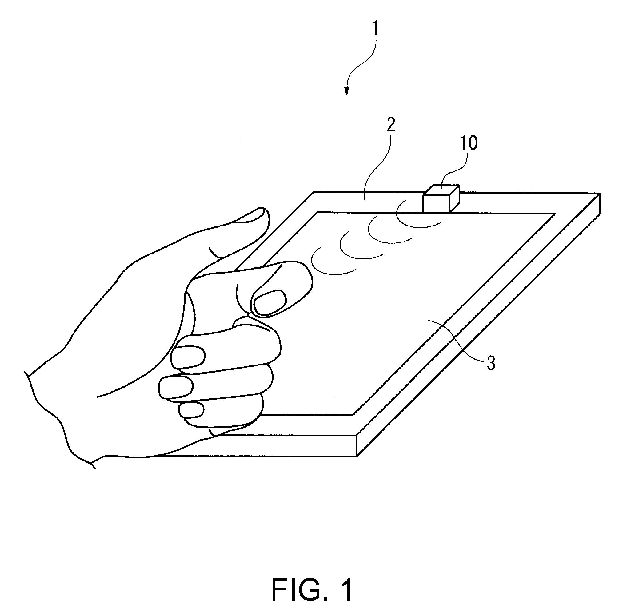
[0053]A first embodiment of the invention will hereinafter be explained with reference to the accompanying drawings. It should be noted that the scale ratios of the layers and the members are set differently in each of the drawings below in order for illustrating the layers and the members in visible sizes on the drawings. It should also be noted that although in the description below a personal data assistance (PDA) equipped with an ultrasonic sensor incorporating the ultrasonic transducer of the embodiment of the invention will be cited as an example, the invention is not limited thereto, but can be applied to any devices outputting an ultrasonic wave to perform various processes such as a cleaning device for cleaning an object with an ultrasonic wave, or a measuring sensor for performing measurement such as measurement of a distance to an object, measurement of a flow rate, or a nondestructive inspection of plumbing.

1. Configuration of PDA

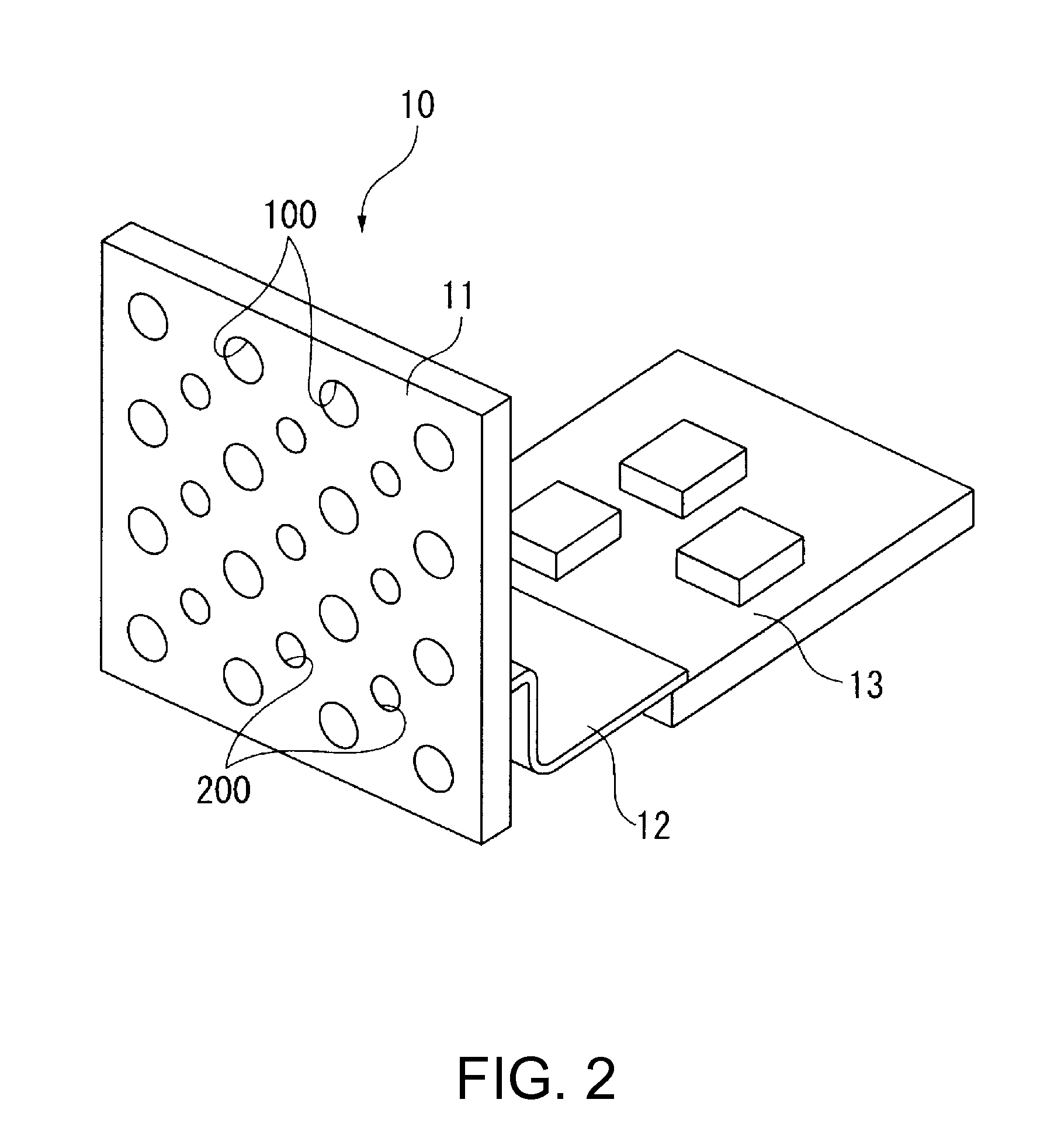
[0054]FIG. 1 is a perspective view schema...

second embodiment

[0120]Then, an ultrasonic sensor according to a second embodiment of the invention will be explained with reference to the accompanying drawings.

[0121]The ultrasonic sensor according to the second embodiment has a sensor array structure obtained by modifying the sensor array structure of the ultrasonic sensor 10 of the PDA 1 according to the first embodiment, and the specific configurations of the ultrasonic transducers 100 and the receiver transducers 200 as second ultrasonic transducers are the same. Therefore, the array structure of the ultrasonic sensor 10A according to the second embodiment will hereinafter be explained.

[0122]As shown in FIG. 13A, the ultrasonic sensor 10A according to the second embodiment is provided with two sensor array substrates, namely an ultrasonic wave transmitting sensor array substrate 11A, and an ultrasonic wave receiving sensor array substrate 11B.

[0123]The ultrasonic wave transmitting sensor array substrate 11A is formed of, for example, a single ...

modified example

[0131]It should be noted that the invention is not limited to the embodiments described above but includes modifications and improvements within a range where the advantages of the invention can be achieved.

[0132]For example, although in the embodiment described above, there is shown an example in which the piezoelectric member 130 is provided with the circular communicating holes 134 formed along the outer periphery of the concave groove section 122, the invention is not limited thereto, but the shapes shown in FIGS. 14A through 14D, for example, can also be adopted. It should be noted that FIGS. 14A through 14D, and FIGS. 15A through 15D, and 16 explained hereinafter show the constituents in a simplified manner, and illustrations of the SiO2 layer 120A, the ZrO2 layer 120B of the diaphragm 120, and illustrations of the piezoelectric film 131, the lower electrode 132, and the upper electrode 133 of the piezoelectric member 130 will be omitted.

[0133]Specifically, as shown in FIGS. 1...


PUM

PropertyMeasurementUnit
thicknessaaaaaaaaaa
thicknessaaaaaaaaaa
thicknessaaaaaaaaaa

Abstract

An ultrasonic transducer includes: a support member having an opening section; a diaphragm adapted to cover the opening section; and a piezoelectric member provided to the diaphragm and at least one of expanding and contracting in an in-plane direction in response to application of a voltage, wherein the diaphragm has a concave groove section formed to have a concave shape on a surface on an opposite side to one side exposed to the opening section, and the piezoelectric member is fixed to the diaphragm in an area outside the concave groove section, and disposed to cover the concave groove section so as to be opposed to a bottom of the concave groove section via a space.

Description

BACKGROUND[0001]1. Technical Field[0002]The present invention relates to an ultrasonic transducer for converting a voltage signal into an ultrasonic wave, an ultrasonic sensor, a method of manufacturing an ultrasonic transducer, and a method of manufacturing an ultrasonic sensor.[0003]2. Related Art[0004]In the past, there has been known micro electromechanical systems (MEMS) provided with ultrasonic transducers for outputting ultrasonic waves. Since the ultrasonic transducers provided to such MEMS are formed to have extremely small sizes, and therefore have thin film piezoelectric members used as sources of ultrasonic waves, and are typically configured to output the ultrasonic waves by displacing diaphragms using vibration of the thin film piezoelectric members (see, e.g., JP-A-2006-319945 (Document 1)).[0005]The diaphragm-type ultrasonic sensor element described in Document 1 is provided with a diaphragm having a multilayer structure, and a PZT ceramic thin film layer provided to...

Claims


Application Information

Patent Timeline
Patent Type & Authority Applications(United States)
IPC IPC(8): B06B1/06H01L41/22H04R17/00
CPCG10K9/122Y10T29/42H01L41/0973H01L41/0926H10N30/2047H10N30/204
Inventor NAKAMURA, TOMOAKINISHIWAKI, TSUTOMU
Owner SEIKO EPSON CORP
Why Eureka
Try Eureka