Force sensors

a technology of force sensors and sensors, applied in the field of force sensors, can solve the problems of high cost, high cost, and high cost of force sensors based on conventional strain gauges, and achieve the effect of low stiffness

Inactive Publication Date: 2006-05-23
NORTHWESTERN UNIV
View PDF10 Cites 40 Cited by
  • Summary
  • Abstract
  • Description
  • Claims
  • Application Information

AI Technical Summary

Benefits of technology

[0008]In accordance with the present invention, the disadvantages of prior force sensors for measuring force and / or torque have been overcome. The force sensor of the present invention is capable of measuring force and torque with respect to a single axis or multiple axes. The force sensor utilizes a flexure element having low stiffness and displacement measuring elements that are sensitive to relatively large displacements. The multi-axis force sensor of the present invention is adaptable to fabrication or manufacture over a wide range of sizes, from the scale of micro-electromechanical systems (MEMS) to the scale of a human hand or even larger.

Problems solved by technology

Force sensors that are suitable for industrial applications such as in robot end-effectors or machining stations are typically based on strain gauges and may be very expensive.
While the strain gauge elements themselves may not be expensive, the difficulty of applying and calibrating strain gauges in force sensor applications results in costly devices.
These types of force sensors based on conventional strain gauges designed for use in industrial applications, however, are overdesigned for use in measuring human inputs and may be unnecessarily costly.
As such, the requirements for these conventional force sensors are unnecessarily stringent for devices used in other applications, such as for interactive human use.
In addition, industrial force sensors are also very rugged and stiff such that applying a force to them causes little or no perceptible deflection.
A typical joystick, however, is not rugged or reliable enough to be utilized in an industrial application where the device may become damaged through constant handling and use.
The reliability of the control device is also an important factor in an industrial application where a failure of the joystick may result in the loss of control of machinery that may cause an accident and injure nearby personnel or workers.

Method used


Image

  • Force sensors
  • Force sensors
  • Force sensors

Examples


Embodiment Construction

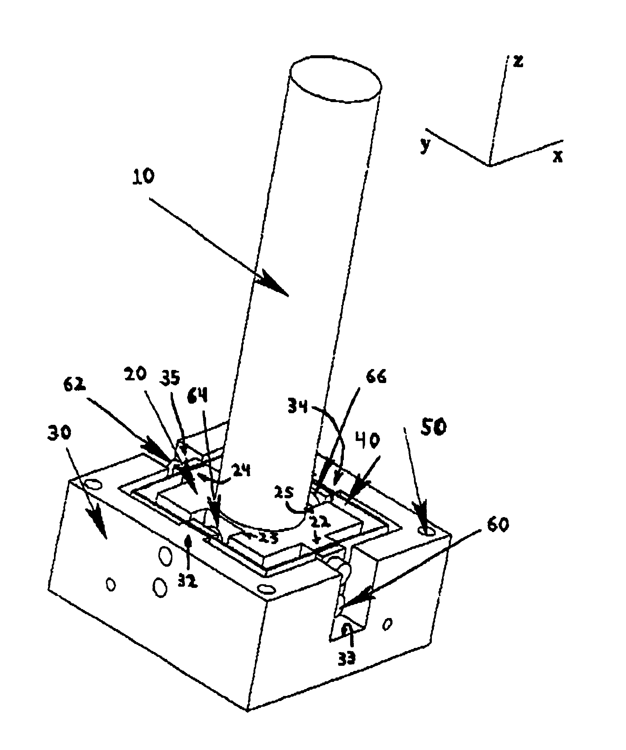
[0049]One embodiment of a force sensor of the present invention as shown in FIG. 1 is used to measure forces applied along different directional axes. This embodiment is particularly designed to accommodate manual control input from a human operator.

[0050]Generally, a force to be measured has components along three axes, the x, y and z axes. In addition, the force to be measured may be a torque or movement about the x, y or z axis. A force sensor may measure these six components of force / torque or a subset thereof. It is noted that as used herein, the term force includes torque about one or more axes as well as force components along one or more axes.

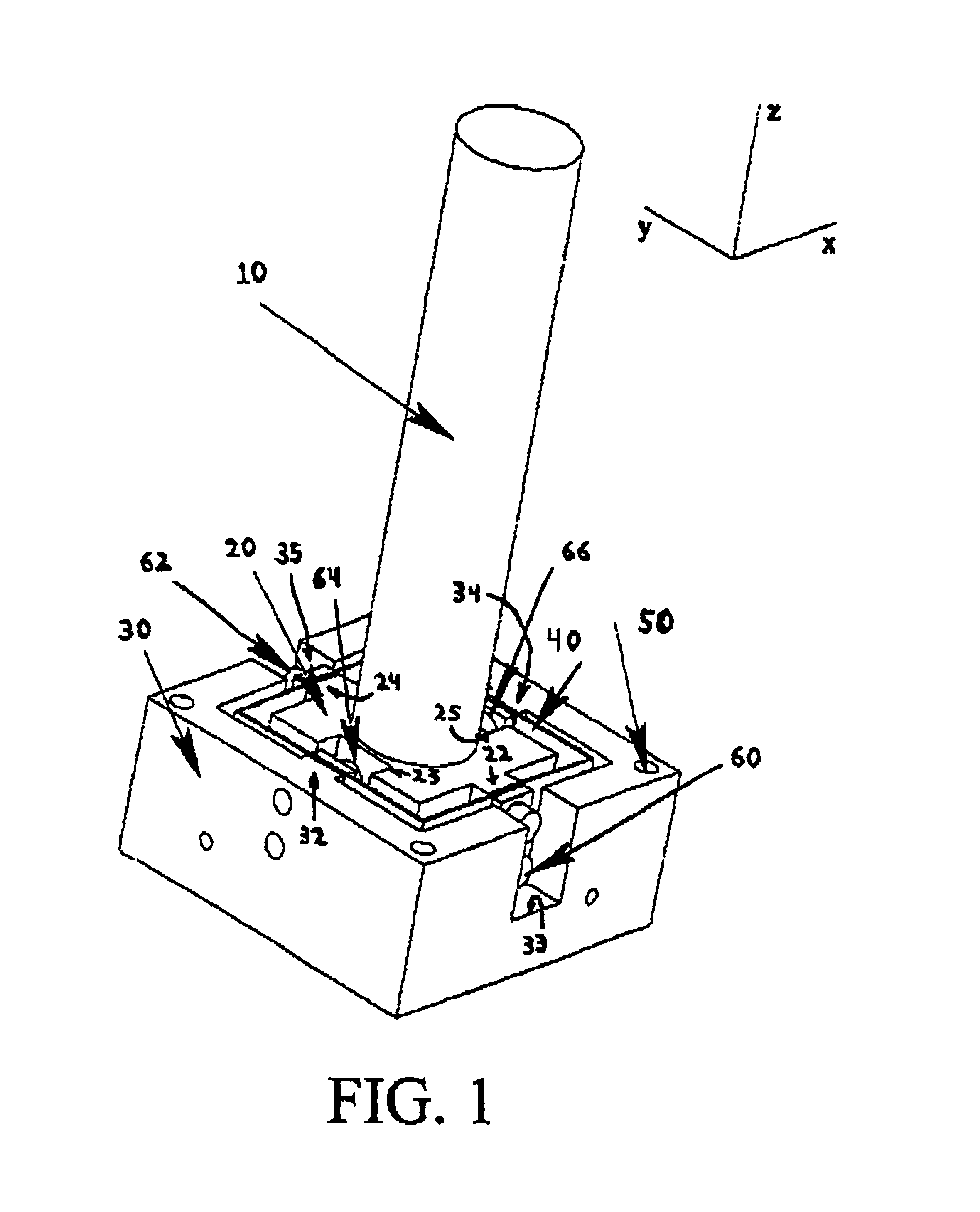
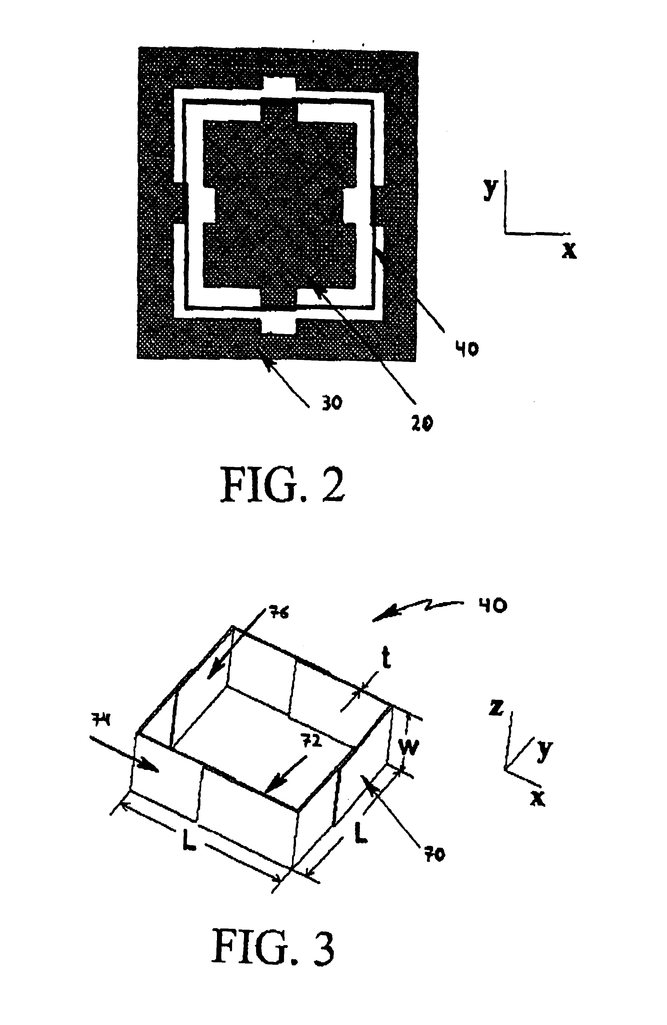
[0051]An embodiment of a two-axis force sensor as shown in FIG. 1 includes a first member 20, and second member 30, and a flexure 40 positioned between the first member 20 and the second member 30. For purposes of the following embodiments, the first member 20 is preferably an inner member 20 while the second member 30 is preferably an ...


PUM

PropertyMeasurementUnit
distanceaaaaaaaaaa
displacementaaaaaaaaaa
aspect ratioaaaaaaaaaa

Abstract

A force sensor for measuring force and/or torque about a single axis or multiple axes is rugged, inexpensive and can be fabricated over a wide range of sizes. The force sensor includes first and second members that are coupled to each other by an elastomeric flexure that allows at least one member to be movable with respect to the other member when a force is applied. The force sensor includes a transmitting coil or printed circuit trace and a receiving coil or printed circuit trace. In one embodiment, the transmitting and receiving coils are formed on different ones of the first and second members. In another embodiment, the transmitting and receiving coils are formed on the same member and the other member is formed as a shading plate. A signal applied to the transmitting coil induces a signal in the receiving coil that represents the force applied.

Description

CROSS-REFERENCE TO RELATED APPLICATIONS[0001]This application is a continuation-in-part of U.S. patent application Ser. No. 09 / 307,357 filed May 7, 1999 now abandoned.STATEMENT REGARDING FEDERALLY SPONSORED RESEARCH OR DEVELOPMENT[0002]This invention was made with the support of the National Science Foundation (NSF), a Federal Government Agency.TECHNICAL FIELD[0003]The present invention is directed to a force sensor for measuring force and torque for use in industrial, consumer and medical applications and more particularly to a force sensor and more particular to such a force sensor that is extremely rugged and easy to manufacture.BACKGROUND OF THE INVENTION[0004]Force sensors are typically used in industrial applications to measure applied forces. Force sensors that are suitable for industrial applications such as in robot end-effectors or machining stations are typically based on strain gauges and may be very expensive. While the strain gauge elements themselves may not be expens...

Claims


Application Information

Patent Timeline
Patent Type & Authority Patents(United States)
IPC IPC(8): G01L1/06G01D1/00G01L1/14
CPCG01L1/14
Inventor PESHKIN, MICHAEL A.
Owner NORTHWESTERN UNIV
Why Eureka
Try Eureka