Lithographic apparatus, device manufacturing method and device manufactured thereby

a technology of lithographic projection and manufacturing method, which is applied in the direction of printers, aircraft stabilisation by gravity apparatus, and element comparison, etc., can solve the problems of constant additional heat dissipation of current carrying components of linear motors or actuators, and the difficulty of vacuum vacuum providing such a system, etc., to achieve low stiffness, low stiffness, low stiffness

Inactive Publication Date: 2005-01-06
ASML NETHERLANDS BV
View PDF6 Cites 64 Cited by
  • Summary
  • Abstract
  • Description
  • Claims
  • Application Information

AI Technical Summary

Benefits of technology

[0018] According to a further exemplary embodiment of the present invention, an arrangement of magnetic assemblies provides a lower stiffness in the first direction.
[0019] According to a still further exemplary embodiment of the present invention, an arrangement of magnetic assemblies provides a bearing having a low stiffness along the first direction, the second direction, and a third direction perpendicular to both first and second directions. Low stiffness in three directions enables control of the magnet bearing (i.e. maintaining a relative position between the first and second parts in the first and third direction) to be executed with minimal effort by, for example, Lorentz type actuators or linear motors.
[0020] According to an even further exemplary embodiment of the present invention, an arrangement of magnetic assemblies provides a low stiffness in all three directions.
[0021] According to another exemplary embodiment of the present invention, an arrangement of magnetic assemblies provides an increased bearing force that can be obtained due to an increased number of magnets. The required bearing force can also be more evenly distributed. Extending the magnetic assemblies in the third direction results in a more stable bearing with respect to tilt around the second direction.
[0022] According to yet another exemplary embodiment of the present invention, an arrangement of magnetic assemblies results in a more stable bearing with respect to tilt around the third direction because the bearing force is generated as the sum of contributions of the different magnets to this bearing force.
[0023] According to an even further exemplary embodiment of the present invention, an arrangement of magnetic assemblies in which the relative position of at least two or more permanent magnets of at least one of the magnetic assemblies is adjustable allows flexible use of the bearing (e.g. for different loads) and also allows for compensation of mechanical or magnetic tolerances of the magnetic assemblies. The magnets whose relative position is adjustable can be of equal size or of different size.

Problems solved by technology

A drawback of an air bearing support is that it is difficult to provide such a system under vacuum conditions.
A drawback of the linear motor or actuator support is that generation of the required bearing force results in a constant additional heat dissipation in the current carrying components of the linear motor or actuator.

Method used


Image

  • Lithographic apparatus, device manufacturing method and device manufactured thereby
  • Lithographic apparatus, device manufacturing method and device manufactured thereby
  • Lithographic apparatus, device manufacturing method and device manufactured thereby

Examples


Embodiment Construction

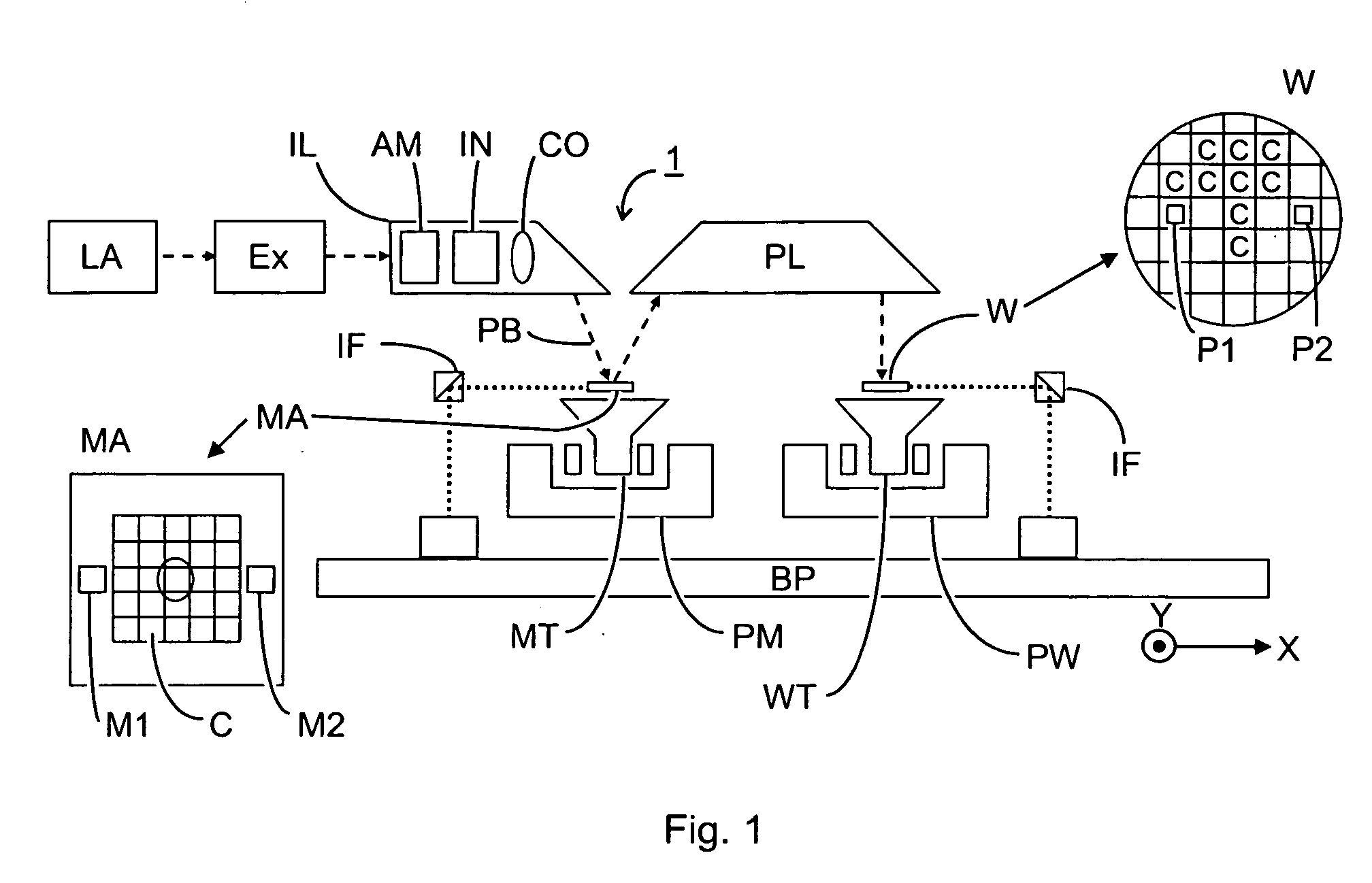
[0053]FIG. 1 schematically depicts a lithographic projection apparatus 1 according to an exemplary embodiment of the present invention. The apparatus includes a radiation system Ex, IL configured to supply a beam PB of radiation (e.g. UV or EUV radiation). The radiation system also includes a radiation source LA. A first object table (mask table) MT is provided with a mask holder configured to hold a mask MA (e.g. a reticle) and is connected to a first positioning device PM that accurately positions the mask with respect to a projection system (“lens”)PL. A second object table (substrate table) WT is provided with a substrate holder configured to hold a substrate W (e.g. a resist-coated silicon wafer) and is connected to a second positioning device PW that accurately positions the substrate with respect to the projection system PL. The projection system PL (e.g. a refractive or catadioptric system, a mirror group or an array of field deflectors) is configured to image an irradiated ...


PUM

PropertyMeasurementUnit
wavelengthaaaaaaaaaa

Abstract

A lithographic projection apparatus includes a passive magnetic bearing configured to provide support between a first and second part of the lithographic apparatus and allow both parts to be displaced relative to each other in a direction perpendicular to the support direction. The passive magnetic bearing includes first and second magnetic assemblies. Each magnetic assembly includes at least one permanent magnet.

Description

BACKGROUND OF THE INVENTION [0001] 1. Field of the Invention [0002] The present invention relates to a lithographic projection apparatus, a device manufacturing method and a device manufactured thereby. [0003] 2. Description of the Related Art [0004] The term “patterning device” as here employed should be broadly interpreted as referring to a device that can be used to endow an incoming radiation beam with a patterned cross-section, corresponding to a pattern that is to be created in a target portion of the substrate. The term “light valve” can also be used in this context. Generally, the pattern will correspond to a particular functional layer in a device being created in the target portion, such as an integrated circuit or other device (see below). Examples of such patterning devices include a mask. The concept of a mask is well known in lithography, and it includes mask types such as binary, alternating phase-shift, and attenuated phase-shift, as well as various hybrid mask types...

Claims


Application Information

Patent Timeline
Patent Type & Authority Applications(United States)
IPC IPC(8): G03F7/20H01L21/027
CPCF16C39/063F16C41/008H02N15/00G03F7/70758G03F7/70725
Inventor DE WEERDT, ROBRECHT EMIEL MARIA LEONIADAMS, JOHANNES ADRIANUS ANTONIUS THEODORUS
Owner ASML NETHERLANDS BV
Why Eureka
Try Eureka