
Braided scaffolds

a scaffold and brad technology, applied in the field of brad or woven stents or scaffolds, can solve the problems of limited fracture toughness, many challenges to overcome, and significant effect on the overall ability of the stent, and achieve the effect of reducing radial strength or stiffness

Inactive Publication Date: 2015-03-19
ABBOTT CARDIOVASCULAR
View PDF7 Cites 61 Cited by
  • Summary
  • Abstract
  • Description
  • Claims
  • Application Information

AI Technical Summary

Benefits of technology

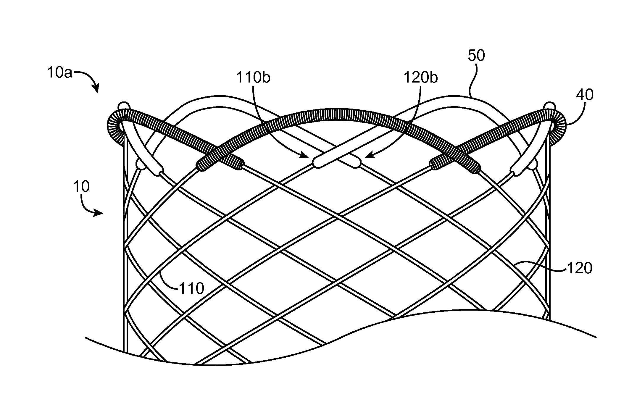
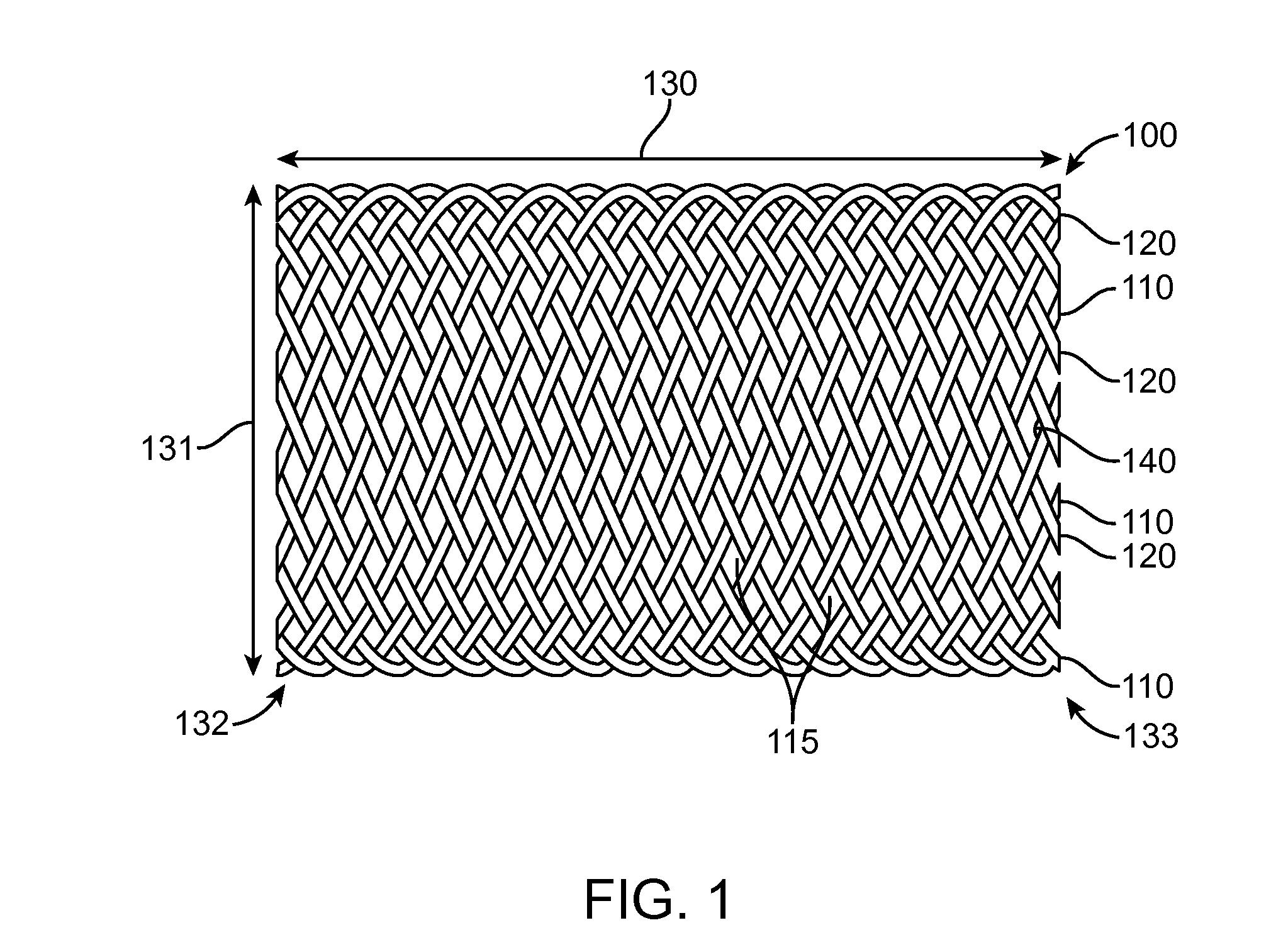
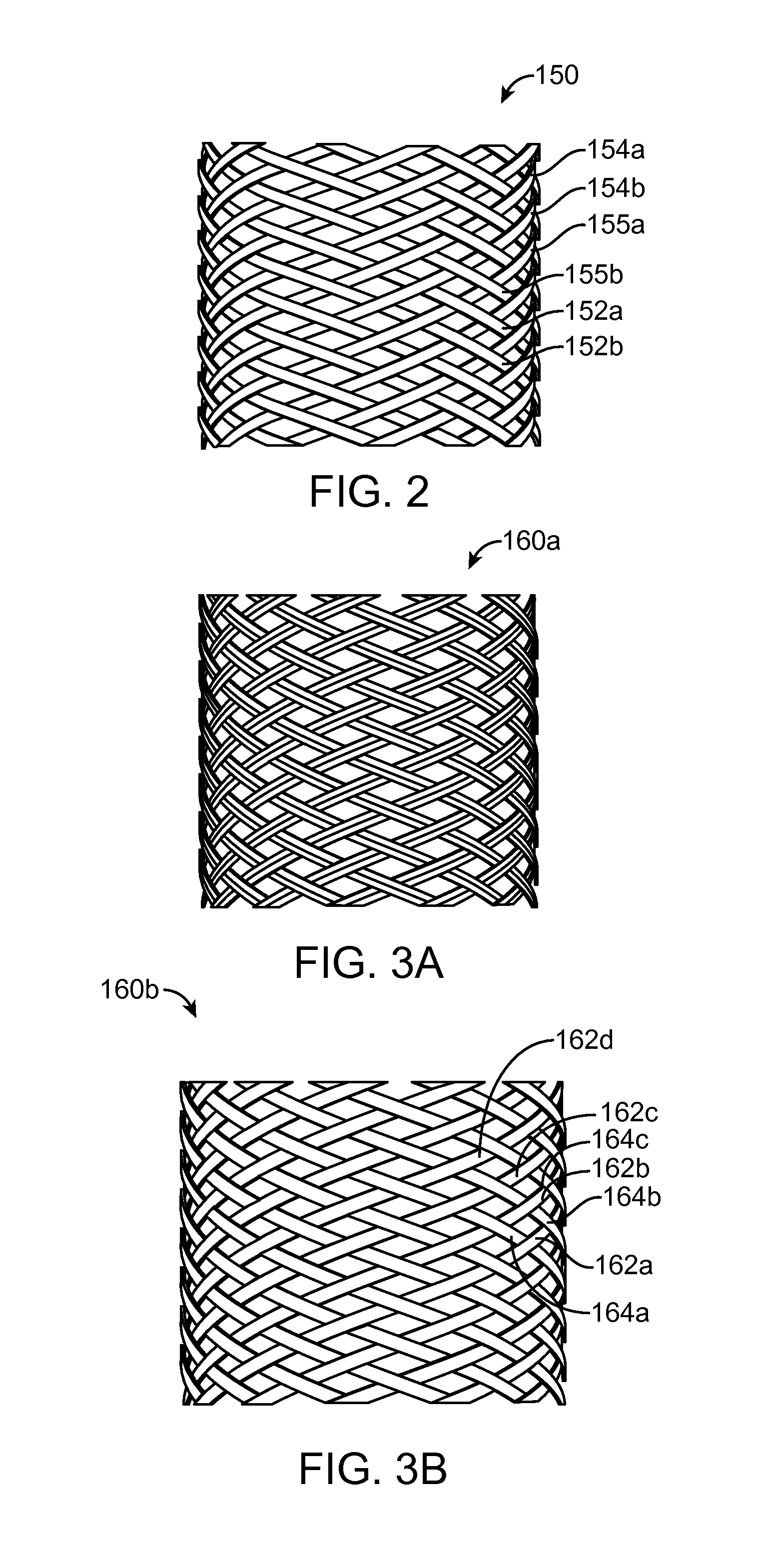
The invention relates to a stent for treating peripheral vessels that provides residual stiffness after deployment. The stent is made of a scaffold that has radial strength or stiffness that decreases with time after deployment. This decreased stiffness can be beneficial in treatments where it is desirable to have a residual stiffness in the treated vessel. The scaffold is made of non-degradable filaments and degradable filaments, which are woven to form a tubular configuration. The non-degradable filaments are made of Nitinol, while the degradable filaments are made of polymers such as poly(L-lactide), poly(L-lactide-co-glycolide), poly(DL-lactide), and polyglycolide. The stiffness or radial strength of the scaffold can vary along its axial length. This decreased stiffness of the scaffold can also reduce compliance mismatch between the scaffold and the vessel.

Problems solved by technology

Even before the radial yield strength is exceeded there may be permanent deformation in the stent following a radial compressive load, but this degree of permanent deformation somewhere in the stent is not severe enough to have a significant effect on the stent's overall ability to radially support a vessel.
However, there are numerous challenges to overcome when developing a polymer scaffold.
The scaffold made from such polymers also tends to be brittle or have limited fracture toughness.
However, scaffolds intended for peripheral vessels experience a quite different loading, to such an extent that the traditional measure of a stent's fitness for use, i.e., its radial strength / stiffness, is not an accurate measure of whether the scaffold will have sufficient strength to provide mechanical support within the peripheral vessel for the duration needed.

Method used


Image

  • Braided scaffolds
  • Braided scaffolds
  • Braided scaffolds

Examples


example 1

[0165]To achieve an appropriate fit for this type of vasculature, one may have the free-standing radii for scaffolds 201, 202 and 203 the same (i.e., R1=R2=R3) and equal to or greater than V3, V2, and V1, and the coverage lengths (Z) for the three scaffolds the same (i.e., L1=L2=L3, respectively, FIG. 21). With these dimensions selected, one can then, utilizing the above relationships, choose a suitable scaffold segment type for each vessel portion to avoid a chronic outward force condition for the narrowed parts of the vasculature.

[0166]One can adjust the fiber length (S) or the free-standing length (Zi) (or both) to achieve the same radial force acting on the vessel for the scaffolds 201, 202 and 203 compressed to different diameters. Thus, for Zi constant and V1>V2>V3 the fiber lengths are S1>S2>S3. Or, alternatively, for S constant and V1>V2>V3 the free-standing lengths are Z1<Z2<Z3.

example 2

[0167]for equal coverage lengths (Z1=Z2=Z3), increasing braid length (S1>S2>S3), and decreasing free-standing radius (R1>R2>R3) EQS. 2, 3A-3B yield the following:[0168]Scaffold 201 values: S / Zi=4, Ri=6.5 mm, Zi=50 mm for L1,[0169]Scaffold 202 values: S / Zi=3.5, Ri=6.0 mm, Zi=50 mm for L2,[0170]Scaffold 203 values: S / Zi=3, Ri=5. mm, Zi=50 mm for L3.

example 3

[0171]For unequal coverage lengths (Z) for the three scaffolds (i.e., L1L2L3, respectively, FIG. 21) vary (S / Zi) to achieve the same radial force acting on the vessel for each scaffold having a different coverage length and deployed in vessel having variable radius.


PUM

PropertyMeasurementUnit
Fractionaaaaaaaaaa
Timeaaaaaaaaaa
Fractionaaaaaaaaaa

Abstract

A braided polymeric scaffold, made at least in part from a bioresorbable material is deployed on a catheter that uses a push-pull mechanism to deploy the scaffold. A drug coating is disposed on the scaffold. A plurality of scaffold segments on a catheter is also disclosed.

Description

[0001]The application claims priority to U.S. Provisional application No. 61 / 877,910 filed Sep. 13, 2013 (docket: 104584.76) and U.S. Provisional application No. 61 / 945,745 filed Feb. 27, 2014 (docket: 104584.88), the entire contents of each of these provisional applications is hereby incorporated by reference for all purposes.FIELD OF INVENTION[0002]The present invention relates to braided or woven stents or scaffolds for treatment of peripheral vessels, such as the superficial femoral artery.BACKGROUND OF THE INVENTION[0003]Radially expandable endoprostheses are artificial devices adapted to be implanted or deployed in an anatomical lumen. An “anatomical lumen” refers to a cavity, duct, of a tubular organ such as a blood vessel, urinary tract, and bile duct. Stents are examples of endoprostheses that are generally cylindrical in shape and function to hold open and sometimes expand a segment of an anatomical lumen (one example of a stent is found in U.S. Pat. No. 6,066,167 to Lau e...

Claims


Application Information

Patent Timeline
IPC IPC(8): A61L31/14A61F2/88
CPCA61F2/88A61L31/148A61F2/90A61F2/966A61F2002/826A61F2250/0018A61F2250/0031A61F2250/0039A61F2250/0067A61L31/128A61F2/9517C08L67/04
Inventor HOSSAINY, SYED FAIYAZ AHMEDPAPP, JOHN E.HARRINGTON, JOEL
Owner ABBOTT CARDIOVASCULAR
Learn More