Elevator Installation with a Support Means End Connection and a Support Means, and a Method of Fastening an End of a Support Means in an Elevator Installation

a technology of support means and elevators, which is applied in the direction of elevators, mine lifts, textile cables, etc., can solve the problem of limited support force of support means, and achieve the effect of good force introduction

Inactive Publication Date: 2007-01-25
INVENTIO AG
View PDF13 Cites 92 Cited by
  • Summary
  • Abstract
  • Description
  • Claims
  • Application Information

AI Technical Summary

Benefits of technology

[0030] An advantageous support means end connection of the illustrated kind results in the case of use of a support means in the form of a multiple cable. The support means then consists of at least two cables or cable strands extending at a spacing from one another and the cable casing encloses the cable or cable strand composite and separates the individual cables or cable strands from one another. The support means in that case has a longitudinal structuring, preferably longitudinal grooves. The longitudinal structuring can be an image of an individual cable or cable strand, or a group of cables or cable strands can be fitted in a longitudinal structure. The cable casing can in that case be specially profiled according to the respective desired groove structure. An applicable construction of the wedge pocket or of the wedge is preferably oriented to the kind of longitudinal structuring. This enables provision of a particularly economic support means end connection. With particular advantage an end of the illustrated support means or of the multiple cable is divided up into the individual cable runs or cable strand runs and each cable run or cable strand run is clamped by means of a respectively associated lo

Problems solved by technology

A disadvantage of this construction is that on the one hand the force introduction from the support means end connection to the cable casing of the support means is released solely by the geometry of the wedge, but that the transmission of force from th

Method used


Image

  • Elevator Installation with a Support Means End Connection and a Support Means, and a Method of Fastening an End of a Support Means in an Elevator Installation
  • Elevator Installation with a Support Means End Connection and a Support Means, and a Method of Fastening an End of a Support Means in an Elevator Installation
  • Elevator Installation with a Support Means End Connection and a Support Means, and a Method of Fastening an End of a Support Means in an Elevator Installation

Examples


Embodiment Construction

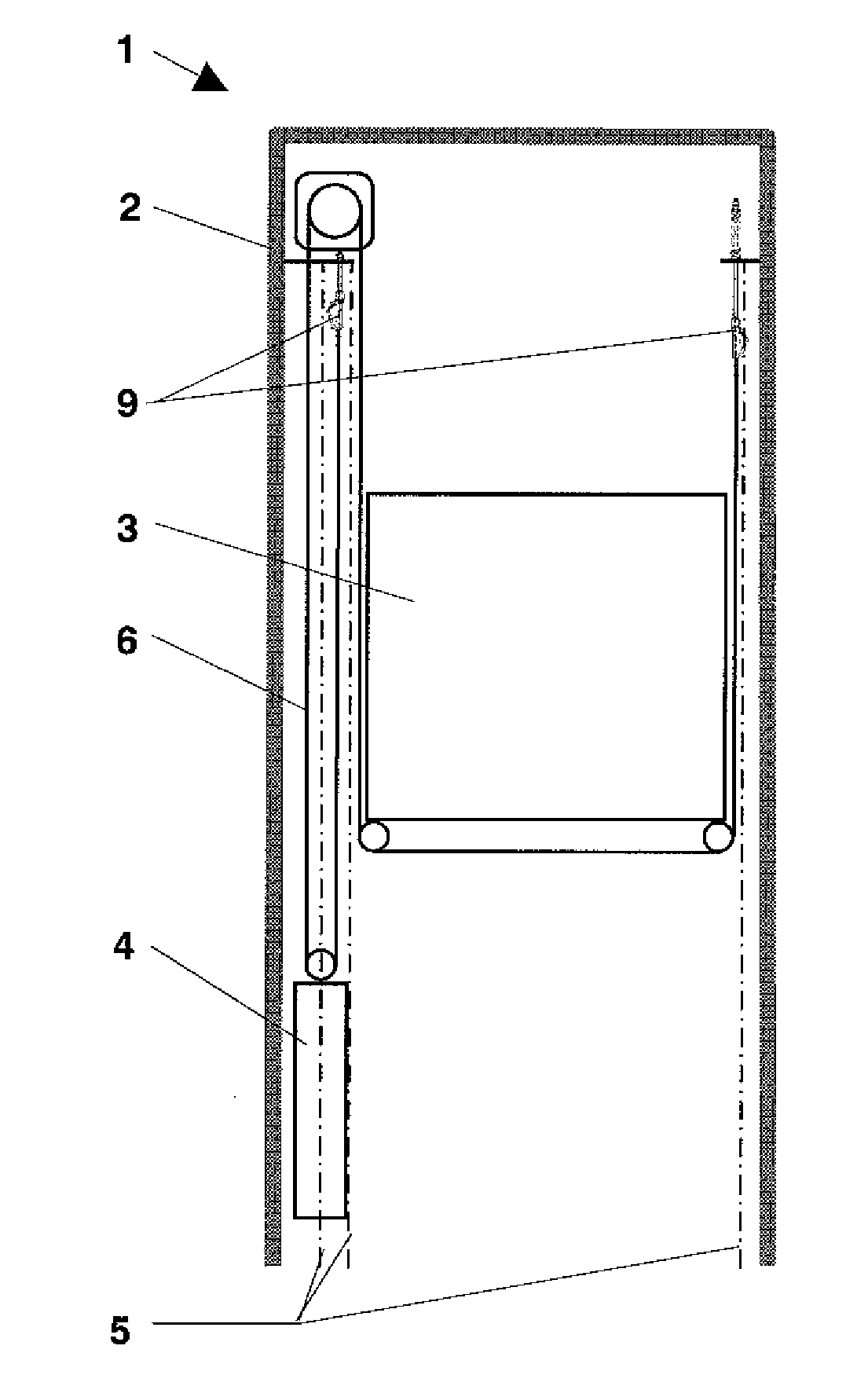
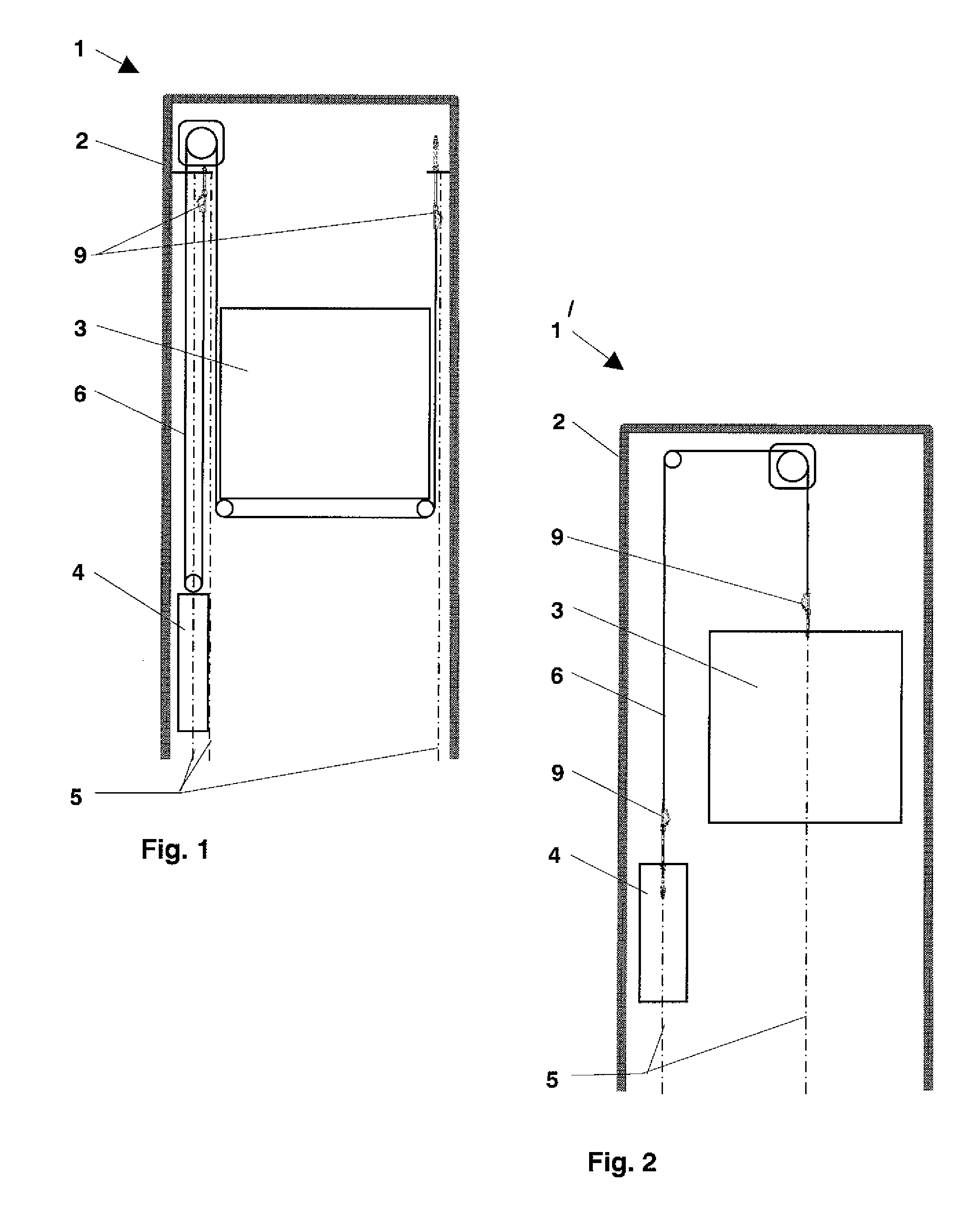
[0048] An elevator installation consists, as illustrated in FIGS. 1 and 2, of a car 3 and a counterweight 4, which are moved in opposite sense in an elevator shaft 2. The car 3 and the counterweight 4 are connected together and supported by way of a support means or device 6. An end of the support means 6 is fastened by a support means end connection 9 to the car 3 or the counterweight 4, according to FIG. 2, or in the elevator shaft 2, according to FIG. 1. The location of the fastening is oriented towards the mode of construction of the elevator installation. FIG. 1 shows this connection for an elevator installation 1 suspended 2:1 and FIG. 2 shows this connection for an elevator installation 1′ suspended 1:1. Axes 5 represent the direction of the loads imposed on the connections 9 by the car 3 and the counterweight 4.

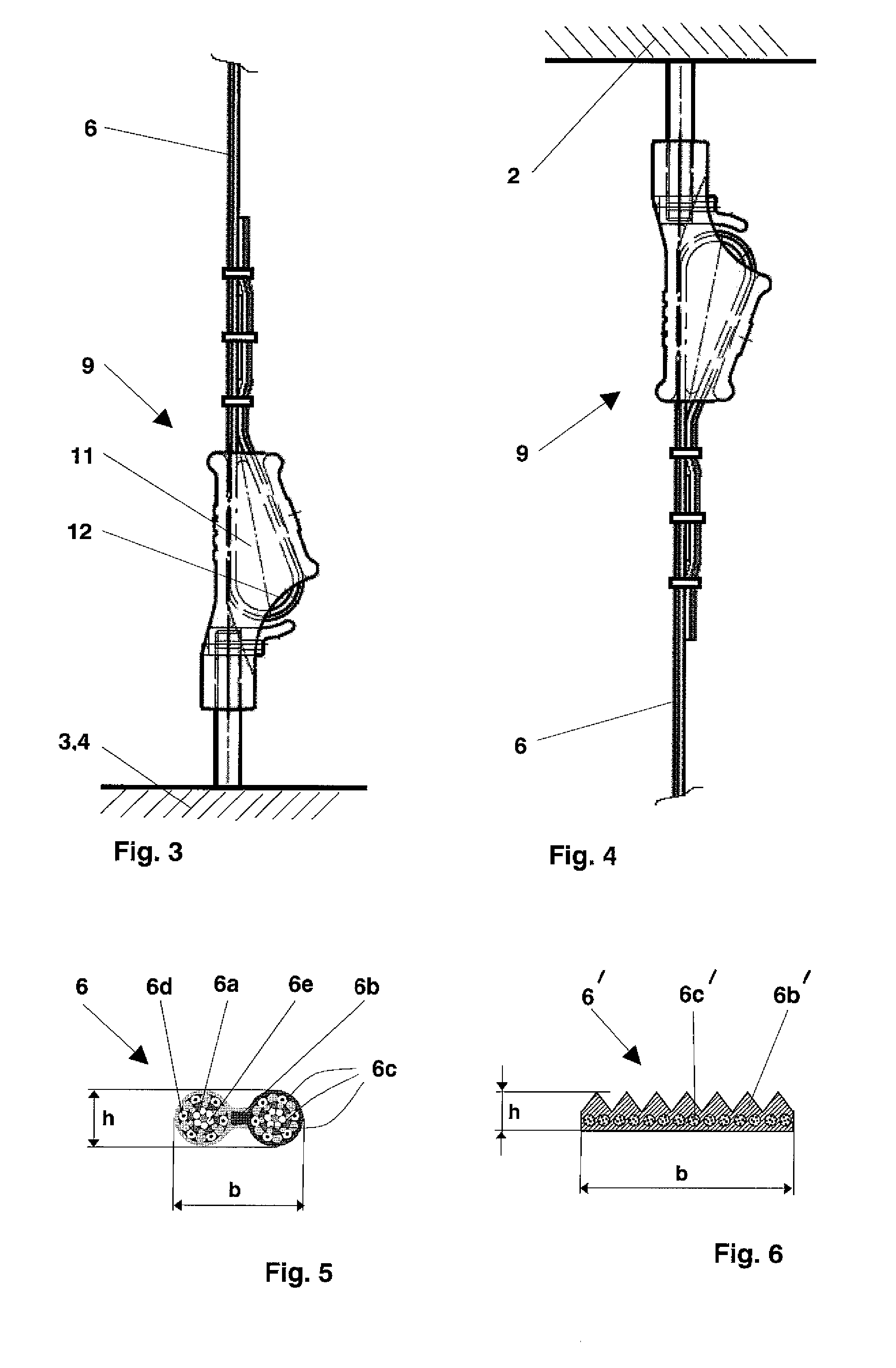
[0049] In FIGS. 3 and 4 it is apparent how the support means 6 is held in the support means end connection 9 by means of a wedge 12, which fixes the support means in...


PUM


Abstract

In an elevator installation, an apparatus and a method use a support end connection for fastening a support device to an elevator car, a counterweight and/or a building. The support device has at least one cable or cable strand enclosed by a cable casing and is held in a wedge pocket by a wedge. The cable casing is formed of thermoplastic material or an elastomer and at least one of a region of the wedge or the wedge pocket is provided with a longitudinal wedge groove and a region of the wedge, of the wedge pocket or the cable casing has a reduced coefficient of friction. The support device is preferably a multiple cable.

Description

BACKGROUND OF THE INVENTION [0001] The present invention relates to an elevator installation with a support means end connection and a support means and to a method of fastening an end of a support means in an elevator installation. [0002] An elevator installation usually consists of a car and a counterweight, which are moved in opposite sense in an elevator shaft. The car and the counterweight are connected together and supported by way of support means. An end of the support means is fastened by a support means end connection to the car or to the counterweight or in the elevator shaft. The location of the fastening is oriented towards the mode of construction of the elevator installation. The support means end connection accordingly has to transmit the force, which acts in the support means, to the car or the counterweight or to the elevator shaft. It has to be designed in such a manner that it can transmit a required supporting force of the support means. [0003] Currently, use is...

Claims


Application Information

Patent Timeline
IPC IPC(8): B66B11/04
CPCF16G11/046B66B7/085B66B7/06B66B7/08B66B11/06B66B19/02
Inventor DOLD, FLORIANBISSIG, ADOLFWIRTH, MANFREDACH, ERNSTDE ANGELIS, CLAUDIO
Owner INVENTIO AG
Why Eureka
Try Eureka