
Apparatus for connecting in parallel a plurality of battery cells which are arranged parallel to one another with respect to a joining axis

a battery cell and parallel technology, applied in the direction of secondary cell details, sustainable manufacturing/processing, batteries, etc., can solve the problems of unfavorable electrical operation conditions, successive damage to the battery cell jacket and/or the oxidation-preventing coating of the contact spring, and difficult assembly procedures

Pending Publication Date: 2022-06-02
JOHN DEERE ELECTRIC POWERTRAIN LLC
View PDF0 Cites 0 Cited by
  • Summary
  • Abstract
  • Description
  • Claims
  • Application Information

AI Technical Summary

Benefits of technology

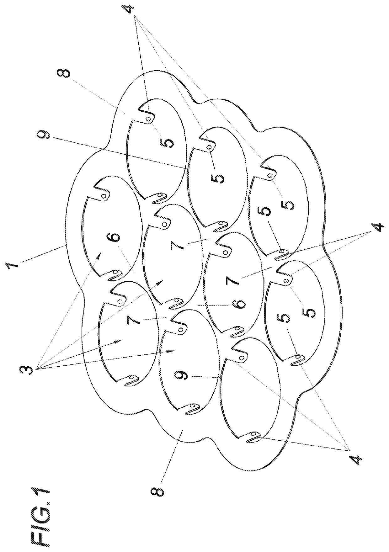
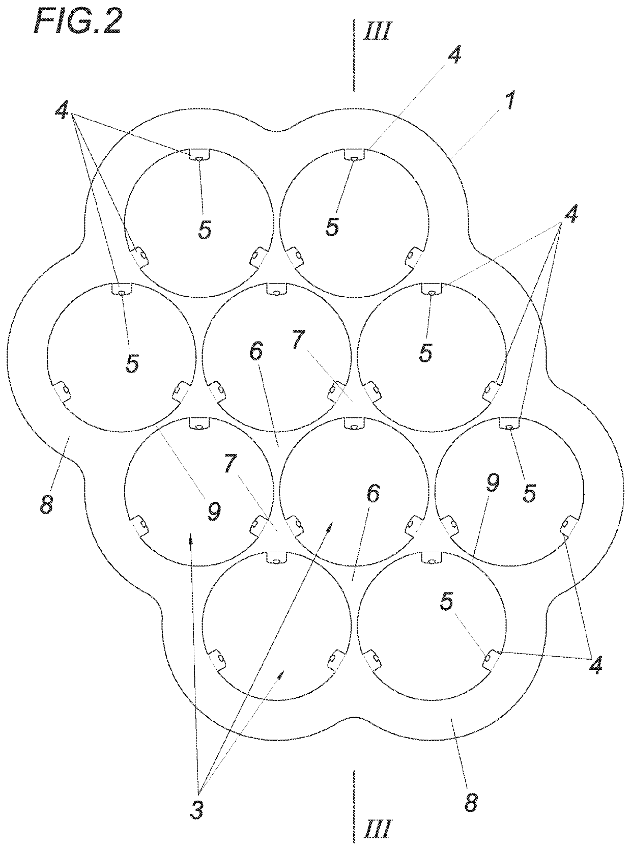
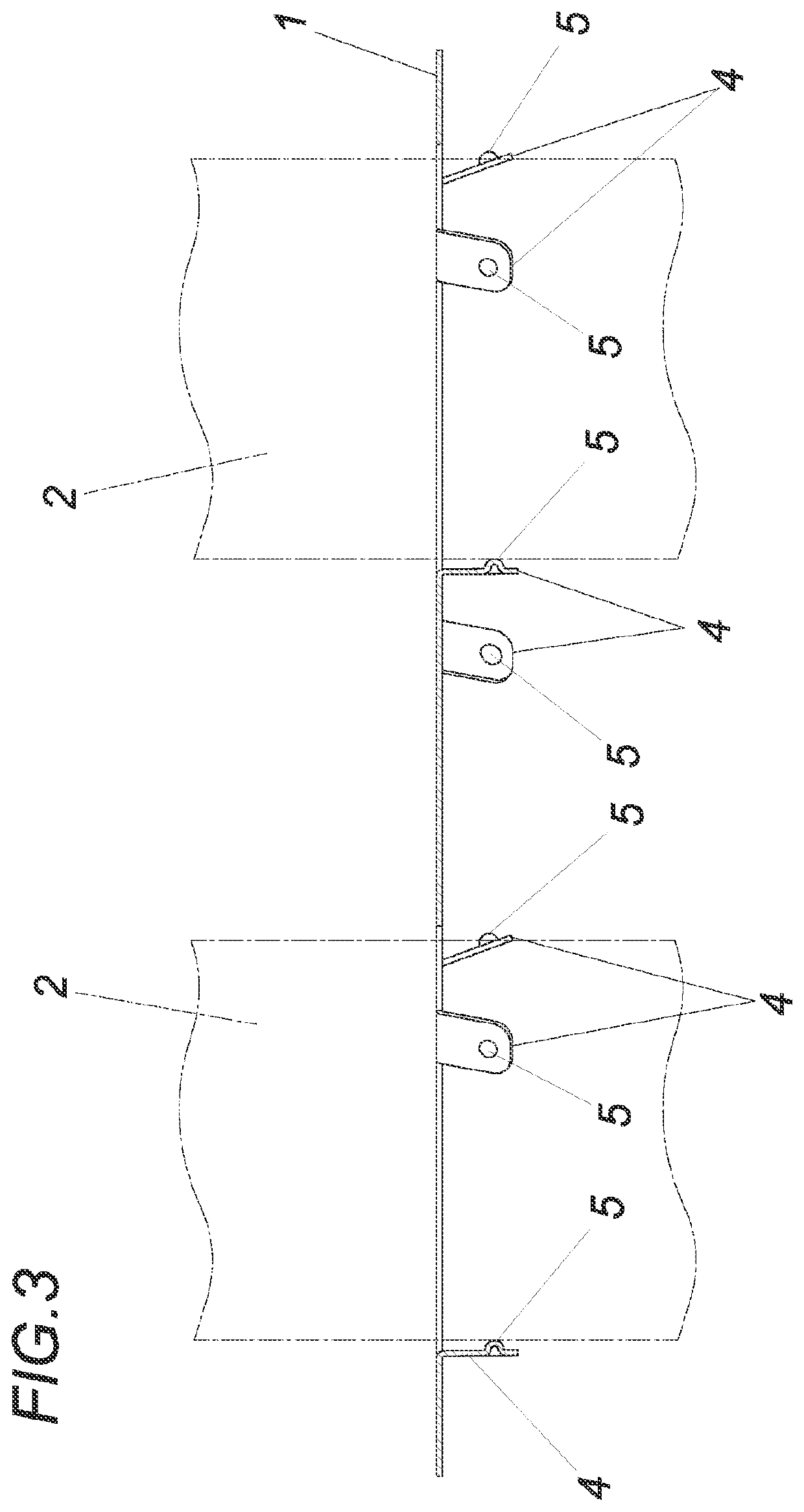
The invention is a contact plate for battery cells that improves electrical contact and stability under mechanical deformation. The contact plate has passages designed to fit the battery cells, with contact tongues that provide a defined contact resistance. The contact body is formed in a way that avoids surface damage and can be coated for better electrical conductivity. The contact plate can be designed to be more or less elastic or rigid depending on the battery type used. The edge region of the contact plate is formed at least five times wider than the narrowest point between passages to improve stability. The invention allows for improved force introduction and a more durable electrical connection between the battery cells and contact plate.

Problems solved by technology

Although this detachable, friction-locked connection between the battery cells and the contact springs is accompanied by easy assembly and exchangeability of defective battery cells, the disadvantage nonetheless results that the clamping forces required for reliable electrical and mechanical contacting of the battery cells make the assembly procedure more difficult insofar as damage to the battery cell jacket and / or the oxidation-preventing coating of the contact springs occurs during the joining of the battery cells in the contact springs.
Constructive restrictions with respect to the possible battery cell diameter and thus the usable power density result therefrom, in particular for the case in which the battery cells and thus the contact springs are subjected to mechanical stresses, for example, oscillations, which, with the typical sharp-edged design of the contact tongues, results in successive damage to the battery cell jacket and / or the oxidation-preventing coating of the contact springs.
In addition, due to the varying contact areas between the contact tongues and the battery cell jacket, a variable contact resistance results, which is accompanied by unfavorable electrical operating conditions.
However, this has the disadvantage in a comprehensible manner that, neglecting the restrictions in the assembly and the lack of exchangeability of defective battery cells, the currents and temperatures occurring during the welding can result in damage to the battery cells.

Method used


Image

  • Apparatus for connecting in parallel a plurality of battery cells which are arranged parallel to one another with respect to a joining axis
  • Apparatus for connecting in parallel a plurality of battery cells which are arranged parallel to one another with respect to a joining axis
  • Apparatus for connecting in parallel a plurality of battery cells which are arranged parallel to one another with respect to a joining axis

Examples


Embodiment Construction

[0003]The invention is therefore based on the object of designing a device of the type described at the outset so that a connection in parallel, which is reliable under periodic mechanical strains and is nonetheless detachable, of individual battery cells is enabled independently of their diameter and their relative location to the contact plate, wherein a simple assembly procedure is maintained and a more flexibly designed serial interconnection of the battery cells can be enabled.

[0004]The invention achieves the stated object in that each passage is designed for the jacket-side enclosure of the battery cells and comprises at least one contact tongue which has on the passage side a contact body protruding from the contact tongue into the passage in the form of a cut ovoid. In contrast to a contact spring known from the prior art, which would have an undefinable contact surface with the battery cell enclosed by the passage depending on the relative location, due to the provision acc...


PUM


Abstract

A device is described for connecting in parallel multiple battery cells (2) arranged in parallel to one another with respect to a joining axis using a contact plate (1) having individual passages (3). To enable a connection in parallel, which is reliable under periodic mechanical strains and nonetheless detachable, of individual battery cells (2) independently of their diameter and their relative location to the contact plate (1), wherein a simple assembling procedure can be maintained and a more flexibly designed serial interconnection of the battery cells can be enabled, it is proposed that each passage (3) is designed for the jacket-side enclosure of the battery cells (2) and comprises at least one contact tongue (4), which has on the passage side a contact body (5) protruding from the contact tongue (4) into the passage (3) in the form of a cut ovoid.

Description

TECHNICAL AREA[0001]The invention relates to a device for connecting in parallel multiple battery cells arranged in parallel to one another with respect to a joining axis using a contact plate having individual passages.PRIOR ART[0002]Devices for connecting battery cells in parallel are known from the prior art (EP3096372A1), in which individual battery cells arranged in parallel with respect to a joining axis are enclosed on the jacket side by contact springs under pre-tension. To connect the individual battery cells in parallel, the contact springs are connected in a materially bonded manner to a contact plate. Although this detachable, friction-locked connection between the battery cells and the contact springs is accompanied by easy assembly and exchangeability of defective battery cells, the disadvantage nonetheless results that the clamping forces required for reliable electrical and mechanical contacting of the battery cells make the assembly procedure more difficult insofar ...

Claims


Application Information

Patent Timeline
IPC IPC(8): H01M50/512H01M50/503H01M50/50H01M50/524H01M50/526
CPCH01M50/512H01M50/503H01M6/42H01M10/02H01M10/04H01M50/50H01M50/524H01M50/526H01M2220/20Y02E60/10Y02P70/50
Inventor WALDSCHÜTZ, GERHARDSSSCHMUDERMAIER, WOLFGANGDREXLER, FLORIANKASTLER, HELMUT
Owner JOHN DEERE ELECTRIC POWERTRAIN LLC
Learn More