
Hydrogen generator

a generator and hydrogen technology, applied in the field of hydrogen generators, can solve the problems of complicating the structure of the overall fuel cell device, and affecting the efficiency of hydrogen generation, so as to achieve constant and stable hydrogen generation

Inactive Publication Date: 2012-11-13
SAMSUNG ELECTRO MECHANICS CO LTD
View PDF7 Cites 0 Cited by
  • Summary
  • Abstract
  • Description
  • Claims
  • Application Information

AI Technical Summary

Benefits of technology

The present invention provides a hydrogen generator that can generate hydrogen constantly and stably. The generator includes an electrolytic bath, a cover with a hydrogen outlet, a flexible pocket filled with electrolyte, and an electrode part fixed to the cover. The flexible pocket has a flexible part that can expand or contract depending on the capacity of the electrolyte. The flexible part allows the generated hydrogen to be exhausted outward while the electrolyte remains inside. The flexible pocket has an elastic force that matches the consumption rate of the electrolyte. A sealer may be provided between the electrolytic bath and the cover.

Problems solved by technology

However, the RHFC method requires an additional reformer to be installed in a system, thus hindering miniaturization.
Therefore, to attain good reaction efficiency, the RHFC method necessitates an intricate high-temperature system, thereby complicating a structure of an overall fuel cell device and impeding reduction in manufacturing costs thereof.
Moreover, the RHFC method inevitably entails an additional structure for removing the CO gas or CO2 gas, i.e., the byproduct generated during the reforming reaction.
This hinders reduction in an overall volume of the device and in manufacturing costs.
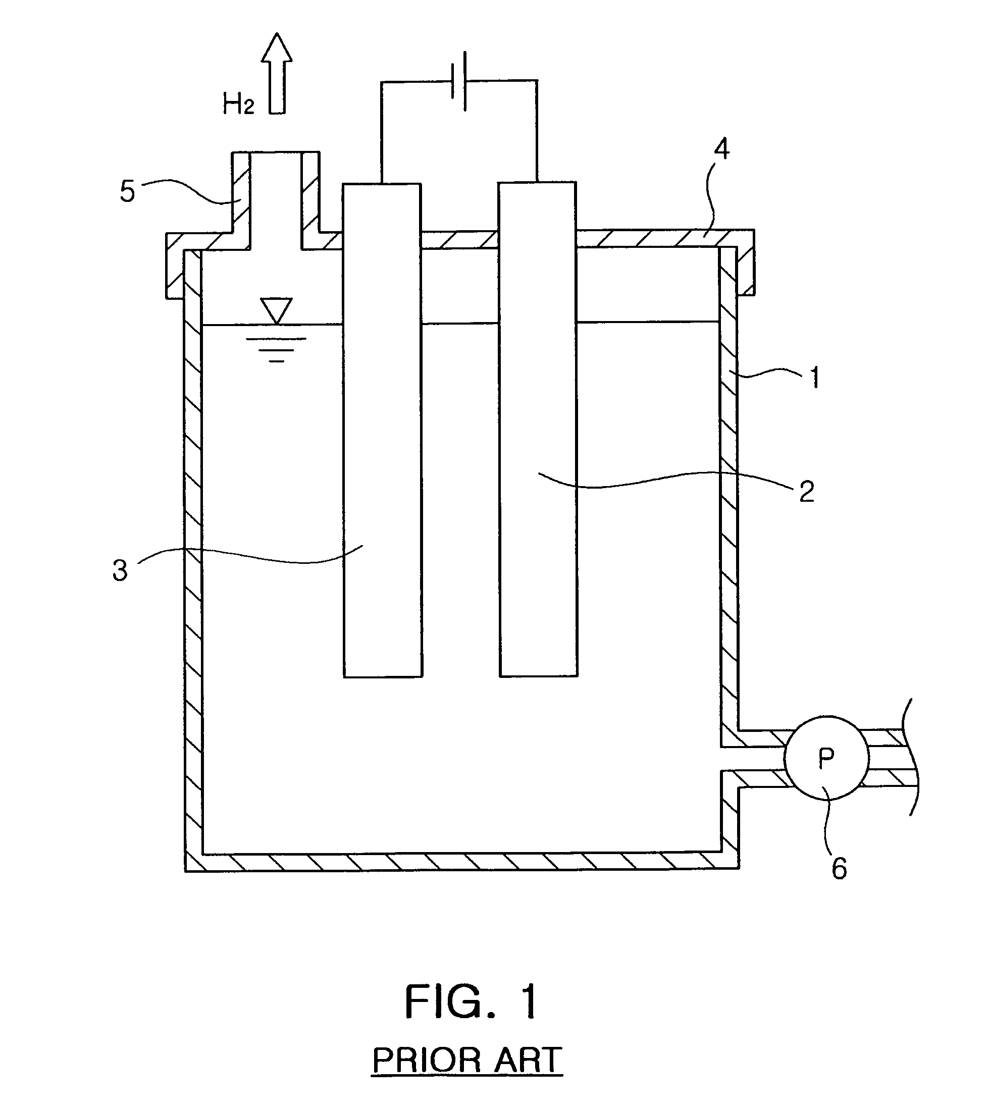
Thus, a fall in the level of the electrolyte of the electrolytic bath leads to a decrease in the amount of hydrogen generated.
In consequence, this hinders downsizing of the device and subsequent miniaturization thereof, and also increases manufacturing costs.

Method used


Image

  • Hydrogen generator
  • Hydrogen generator
  • Hydrogen generator

Examples


Embodiment Construction

[0036]Exemplary embodiments of the present invention will now be described in detail with reference to the accompanying drawings.

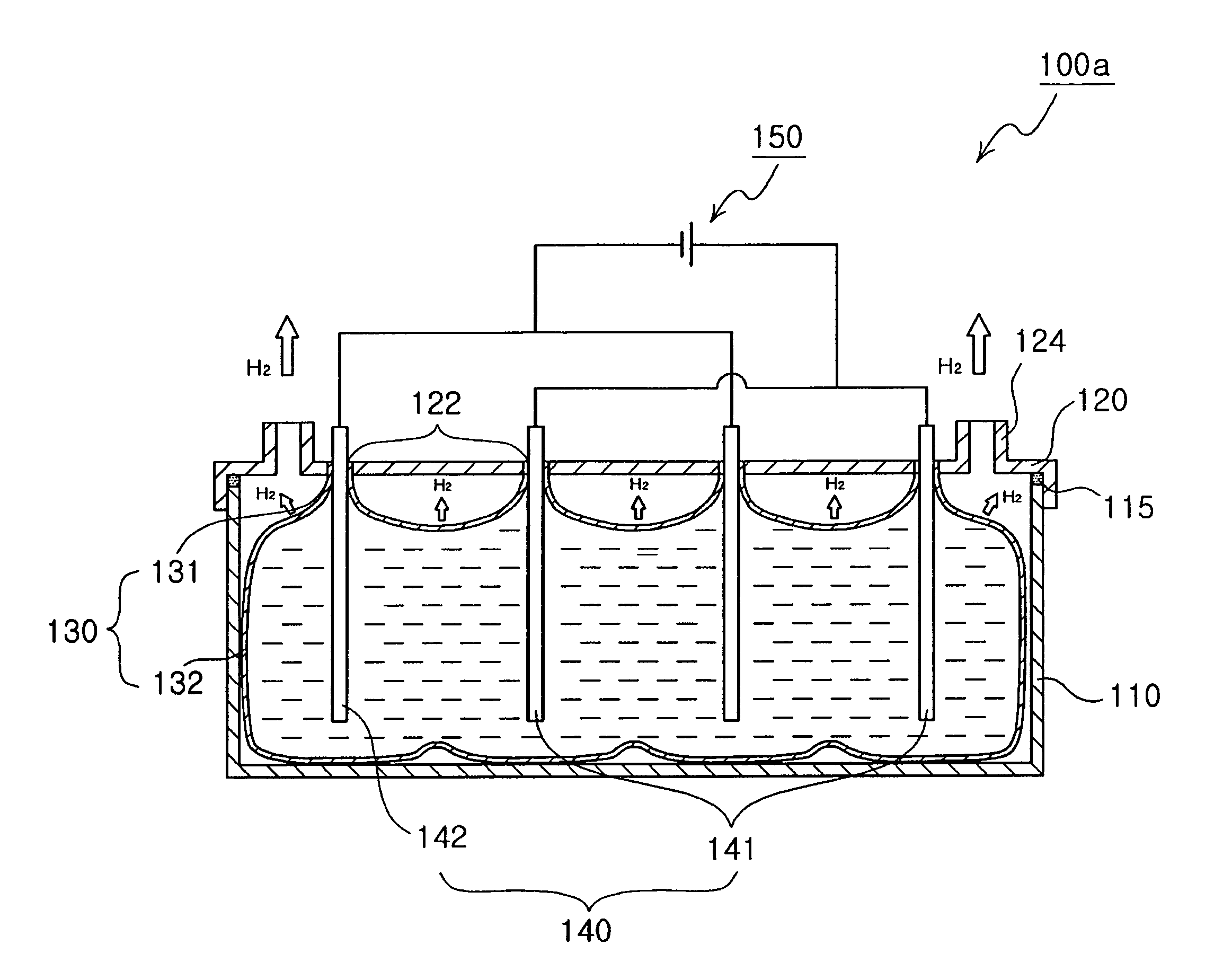
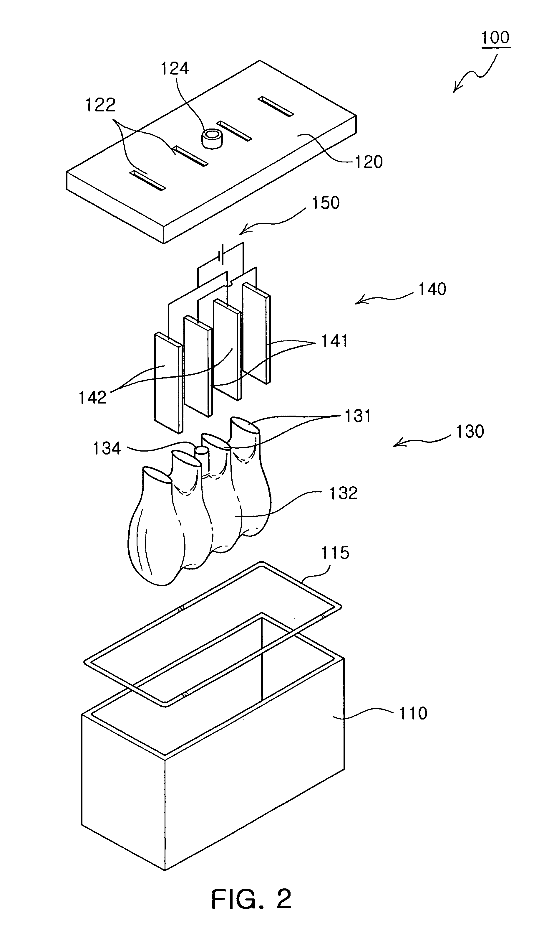
[0037]FIG. 2 is an exploded perspective view illustrating a hydrogen generator according to a first embodiment of the invention. FIG. 3A is a cross-sectional view illustrating an expanded state of a flexible pocket employed in the hydrogen generator of the first embodiment. FIG. 3B is a cross-sectional view illustrating a contracted state of a flexible pocket employed in the hydrogen generator of the first embodiment.

[0038]As shown in FIGS. 2, and 3A and 3B, the hydrogen generator 100 of the first embodiment includes an electrolytic bath 110, a cover 120, a flexible pocket 130, an electrode part 140 and a power supply 150.

[0039]The electrolytic bath 110 is formed of a rectangular parallelepiped box having an inner space of a predetermined size. The cover 120 is a plate-shaped structure attached on the electrolytic bath 110 to hermetically cover an open top...


PUM

PropertyMeasurementUnit
sizeaaaaaaaaaa
flexibleaaaaaaaaaa
currentaaaaaaaaaa

Abstract

There is provided a hydrogen generator. The hydrogen generator including: an electrolytic bath having an inner space of a predetermined size; a cover hermetically covering an open top of the electrolytic bath and having at least one hydrogen outlet; a flexible pocket disposed in the electrolytic bath and filled with an electrolyte of a predetermined amount; an electrode part fixed to the cover, and immersed in the electrolyte filled in the flexible pocket to electrolyze the electrolyte upon application of power; and a power supply supplying current to the electrode part. In the hydrogen generator, the electrode part and the electrolyte maintains a substantially constant contact area there between, thereby allowing hydrogen to be generated constantly and stably.

Description

CROSS-REFERENCE TO RELATED APPLICATIONS[0001]This application claims the priority of Korean Patent Application No. 2007-04663 filed on Jan. 16, 2007, in the Korean Intellectual Property Office, the disclosure of which is incorporated herein by reference.BACKGROUND OF THE INVENTION[0002]1. Field of the Invention[0003]The present invention relates to a hydrogen generator, more particularly, in which electrodes and an electrolyte maintain a substantially constant contact area therebetween, thereby obtaining hydrogen generated during electrolysis of the electrolyte stably per a predetermined time.[0004]2. Description of the Related Art[0005]Recent years have seen an increasing use of small-sized electronic devices such as mobile phones, personal digital assistants (PDAs), digital cameras and laptop computers. Particularly, with the start of digital multimedia broadcasting (DMB) for mobile phones, a small-sized mobile terminal is required to be improved in power capacity.[0006]A lithium-...

Claims


Application Information

Patent Timeline
Patent Type & Authority Patents(United States)
IPC IPC(8): C25B9/00C25B13/00C25B9/19
CPCC25B1/04C25B9/08H01M8/0656Y02E60/366Y02E60/50Y02E60/36C25B9/19C25B1/02
Inventor GIL, JAE HYOUNGJUNG, CHANG RYULJANG, JAE HYUK
Owner SAMSUNG ELECTRO MECHANICS CO LTD
Learn More