
Soil-structure contact surface test soil container

A contact surface and soil container technology, applied in the direction of instruments, scientific instruments, measuring devices, etc., can solve problems such as uneven friction, unclear force, distortion of test results, etc., to achieve the effect of ensuring authenticity and area

Pending Publication Date: 2018-12-21
TSINGHUA UNIV
View PDF9 Cites 0 Cited by
  • Summary
  • Abstract
  • Description
  • Claims
  • Application Information

AI Technical Summary

Problems solved by technology

[0004] 1. Most of the instruments used in the research on the contact surface between soil and structure are improved from the existing geotechnical test instruments. The normal stress is applied on the soil instead of the contact surface. The force is not clear and the concept is not clear. clear
[0005] 2. The current test equipment has the phenomenon of soil strain localization during the test, which leads to distortion of test results and reduced data reliability
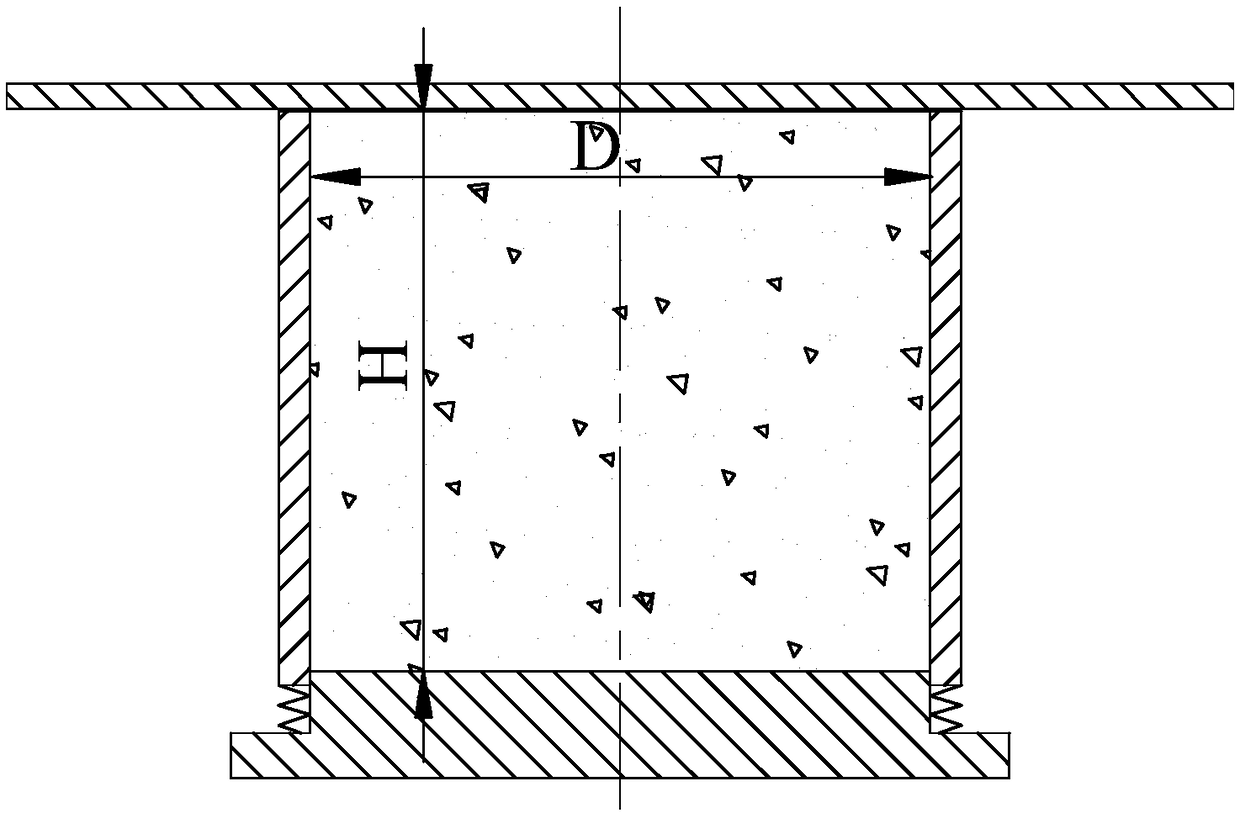
[0007] 1. During the test, there is uneven normal stress between the soil container and the structural panel. When the relative displacement of the soil and the structural panel occurs, there is a large tangential friction force between the structural panel and the soil container, and the friction is not uniform. , which is difficult to calibrate and deduct from the test results, this friction is still acceptable for coarse-grained soils and large samples, but for fine-grained soils or small samples, this soil container and structural panel The friction between the soil sample and the structural panel is unacceptable, and its magnitude may even exceed the friction between the soil sample and the structural panel
This will make it difficult to accurately measure the mechanical properties of the contact surface between the soil and the structural panel, which in turn will lead to distortion of the test results, and the design will be dangerously biased, which will cause great harm to the calculation and design
Even the structural panel and the soil container are stuck due to the frictional self-locking phenomenon, and the soil and the structural panel are separated and cannot be contacted
[0008] 2. During the test, in order to prevent the normal stress generated by the contact between the structural panel and the soil container and then the tangential stress, the upper edge of the soil container is lower than the top surface of the soil sample, resulting in a gap between the upper edge of the soil container and the structural panel. Large gaps, which cause soil particles to escape from the gaps between the structural panels and the soil container during the test, resulting in a reduction in the area of ​​the contact surface

Method used


Image

  • Soil-structure contact surface test soil container
  • Soil-structure contact surface test soil container
  • Soil-structure contact surface test soil container

Examples


Embodiment

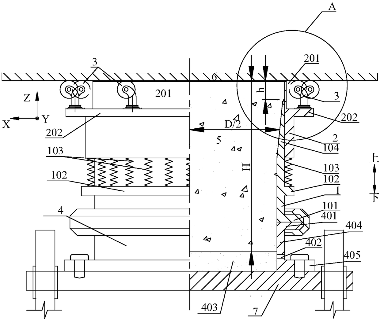
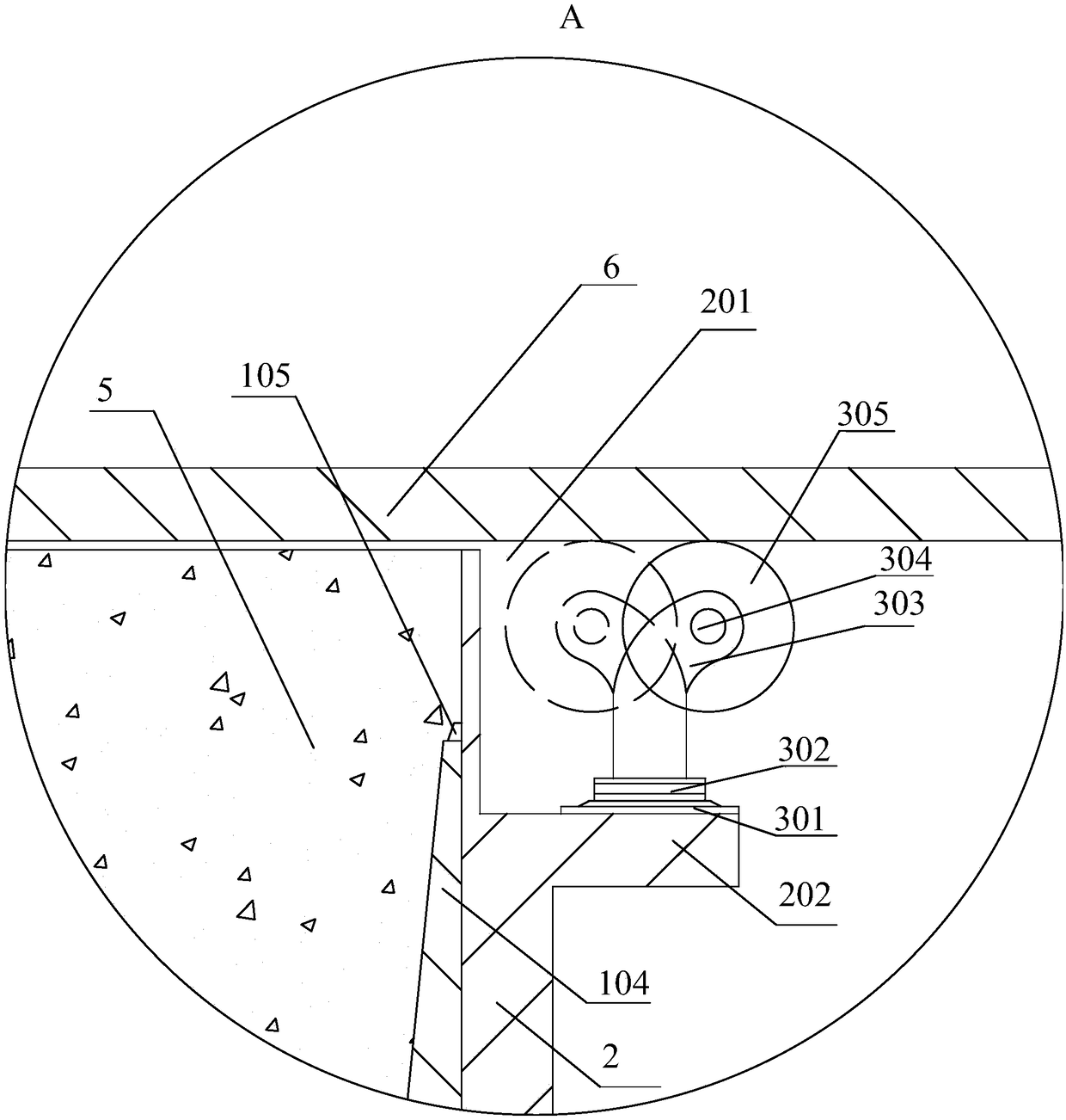
[0048] Refer to the attached Figure 2-3 Describe the soil and structure interface test soil container 100 of a specific embodiment of the present invention, introduce the content of the present invention in detail:

[0049] For the sake of illustration, the Cartesian coordinate system is established as figure 2 As shown in , the X-axis is horizontal to the left, the Y-axis is vertical and outward from the view plane, and the Z-axis is up.

[0050] The soil and structure interface test soil container 100 that present embodiment proposes, its structure is as follows figure 2 As shown, the soil container 100 is installed between the structural panel 6 and the Z-direction bearing plate 7 of the testing machine during use. The soil container 100 includes a soil container seat 4 , a lower barrel 1 , an upper barrel 2 , an elastic member 103 and a rolling member 3 . The bottom of the lower barrel 1 is a soil container seat 4, and the soil container 100 is relatively fixed to th...


PUM


Abstract

The invention discloses a soil-structure contact surface test soil container. The soil container comprises a soil container seat, a lower barrel, an upper barrel, springs and rolling members. The soilcontainer is relatively fixed to the Z-direction carrier plate by the soil container seat; the lower part of the upper barrel is mounted over the upper part of the lower barrel; a rolling member seatand an elastic seat are respectively arranged on outer peripheral walls of the upper barrel and the lower barrel; an elastic member is arranged between the bottom surface of the upper barrel and theelastic seat; the rolling members are fixed to the rolling member seat in the middle of the upper barrel through a base; the rollers of the rolling members are in contact with a structural panel; anda height of the upper end surface of the upper barrel is lower than a height of the top of a roller rim. According to the soil-structure contact surface test soil container, the soil container adoptsa split design for the upper and lower barrel and the rolling members, which reduces tangential friction between the structural panel and the soil container. The friction can be calibrated and deducted to ensure that a result is true and the structural panel and the soil container will not be stuck or disengaged. In addition, a gap between the structural panel and the soil container is adjusted according to a particle size of a soil sample to ensure that the soil sample does not escape from the gap and the contact surface area is unchanged.

Description

technical field [0001] The invention belongs to the technical field of geotechnical testing instruments, in particular to a soil container for soil-structure contact surface testing. Background technique [0002] The study of the mechanical properties of the contact surface between soil and structure is one of the important topics in soil mechanics research, which has a great impact on the calculation, design and construction technology of structures. There are mainly two methods for studying the mechanical properties of soil-structure interface, experimental method and numerical method. At present, the main test instruments used in the test method are direct shear type, simple shear type, torsional shear instrument, dynamic triaxial instrument and resonance column instrument. Among them, direct shear type and simple shear type contact surface test instruments are improved from direct shear instrument and simple shear instrument. Because of their simple principle and conven...

Claims


Application Information

Patent Timeline
Patent Type & Authority Applications(China)
IPC IPC(8): G01N3/02
CPCG01N3/02
Inventor 张建民刘和鑫王睿王贺
Owner TSINGHUA UNIV
Learn More