Method for the manufacture of a fibre composite component, a reinforcement element and also a fibre composite component

a technology of fibre composite components and components, applied in the direction of transportation and packaging, other domestic articles, chemistry apparatus and processes, etc., can solve the problems of increasing assembly costs and the weight of the fuselage shell, and achieve the effect of improving adhesive bonded joints and/or bonding and high loads

Active Publication Date: 2018-06-19
AIRBUS OPERATIONS GMBH
View PDF17 Cites 0 Cited by
  • Summary
  • Abstract
  • Description
  • Claims
  • Application Information

AI Technical Summary

Benefits of technology

[0004]The object of the invention is to create a method for the manufacture of a fibre composite component, which enables an improved adhesive bonded joint and / or bonding of at least one ancillary element to a base element. Furthermore it is the object of the invention to form a reinforcement element for purposes of developing a bonding surface for the at least one ancillary element, and also to create a fibre composite component that can be subjected to high loads.
[0006]The integration of the bonding surface into a separate reinforcement element enables an individual adjustment of the bonding surface independently of the base element. The reinforcement element can consist of separate materials and can have fibre orientations that allow an optimal introduction of force from the ancillary element into the base element and an optimal materially bonded bonding of the ancillary element. Thereby, by the covering or splicing in of the reinforcement element in some sections, an extensive joint is created between the base element and the reinforcement element. By means of the arrangement of the ancillary element in the wet state on the bonding surface a particularly intimate joint is created between the bonding surface and the ancillary element, such that the ancillary element is connected via the reinforcement element to the base element such that it can accommodate high loads. Furthermore the inventive method can be integrated into the existing production process for the base element, without by this means increasing the number of process steps.
[0007]In one example of embodiment the at least one reinforcement element is cured before it is positioned in the bonding region. By this means ease of manipulation and mounting of the reinforcement element is possible.
[0012]Moreover the propagation of delaminations is prevented in the bonding region by means of the reinforcement element.
[0016]The reinforcement element preferably has at least one fibre layer to be removed in the region of the bonding surface. In particular a plurality of fibre layers that are to be removed can provide compensation for component and assembly tolerances. Just one fibre layer represents an effective protection of the fibre layer forming the respective bonding surface.

Problems solved by technology

However, the rivets increase the assembly costs and the weight of the fuselage shell.

Method used


Image

  • Method for the manufacture of a fibre composite component, a reinforcement element and also a fibre composite component
  • Method for the manufacture of a fibre composite component, a reinforcement element and also a fibre composite component
  • Method for the manufacture of a fibre composite component, a reinforcement element and also a fibre composite component

Examples


Embodiment Construction

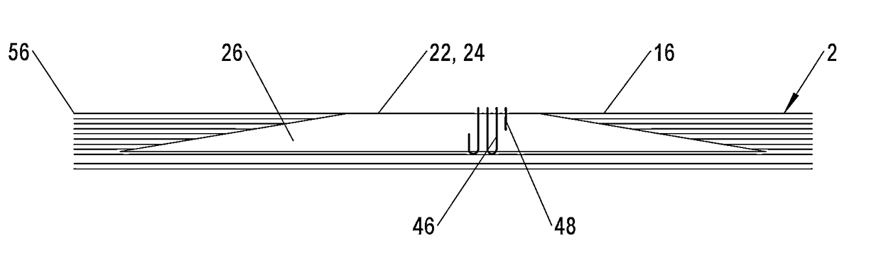
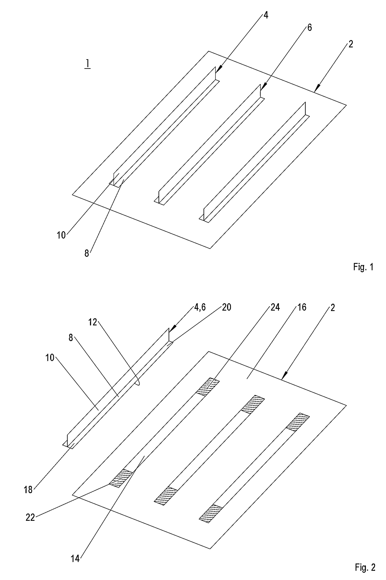
[0032]FIG. 1 shows an inventive fibre composite component 1, with a base element 2, to which a multiplicity of ancillary elements 4, 6 are connected. The fibre composite component 1 is, for example, a shell component, in particular a fuselage shell of an aircraft fuselage, with a skin field, which is stiffened by means of longitudinal stiffeners or stringers, wherein the ancillary elements 4, 6 represent the stringers, and the base element 2 represents the skin field.

[0033]The base element 2 is a shell-type fibre composite element and consists preferably of a multiplicity of fibre webs, which in a laying process such as ATL (Automatic Tape Laying) or FPL (Fibre Placement Laying) have been laid down on a mould surface, not shown, in a plurality of layers and orientations. The fibre webs consist of carbon fibre mats arranged in a thermosetting or thermoplastic resin matrix and are preferably so-called prepregs. Alternatively, however, fibre mats of glass fibres, aramide fibres and sim...


PUM

PropertyMeasurementUnit
resistanceaaaaaaaaaa
weightaaaaaaaaaa
corrosionaaaaaaaaaa

Abstract

A method for the manufacture of a fiber composite component with a base element, and with at least one ancillary element bonded to the base element. A reinforcement element is introduced in at least one bonding region of the base element or the ancillary element for purposes of developing a bonding surface for the ancillary element or the base element. A reinforcement element with fiber sections, the ends of which emanate from a bonding surface is provided. A fiber composite component is provided with a base element, in the bonding regions of which reinforcement elements are introduced, on the bonding surfaces of which ancillary elements are bonded with one such.

Description

CROSS-REFERENCES TO RELATED APPLICATIONS[0001]This application claims the benefit of the U.S. Provisional Application No. 61 / 472,640, filed on Apr. 7, 2011, and of the German patent application No. 10 2011 006 977.1 filed on Apr. 7, 2011, the entire disclosures of which are incorporated herein by way of reference.BACKGROUND OF THE INVENTION[0002]The invention concerns a method for the manufacture of a fibre composite component, a reinforcement element for purposes of developing a bonding surface, and also a fibre composite component manufactured in accordance with such a method.[0003]Shell components (e.g. fuselage and wing shells) of aircraft are composed as a rule from a shell-type skin field and from longitudinal stiffeners. The longitudinal stiffeners or ancillary elements are extensively bonded to the skin field or base element, and transport mainly axial loads. The skin field transports primarily shear loads, wherein by means of the extensive bonding of the longitudinal stiffe...

Claims


Application Information

Patent Timeline
Patent Type & Authority Patents(United States)
IPC IPC(8): B32B38/10B29C70/24B29D99/00B64C1/12B29C70/86B32B5/12B32B7/04B64C1/00B29K105/24B29L31/30
CPCB32B38/10B29C70/24B29C70/86B29D99/001B29D99/0014B32B5/12B64C1/12B32B7/04Y10T428/23914B29K2105/24B29K2105/246B29L2031/3082B29L2031/3085B64C2001/0072Y02T50/40
Inventor ELBRACHT, DIRK
Owner AIRBUS OPERATIONS GMBH
Why Eureka
Try Eureka