Active/passive distributed absorber for vibration and sound radiation control

a distributed absorber and active technology, applied in the field of tunable vibration absorbers, can solve the problems of ineffective low vibration frequency inverting and amplifying the signal, high cost of expensive and complex control systems, and large volume of passive systems

Inactive Publication Date: 2004-03-02
VIRGINIA TECH INTPROP INC
View PDF10 Cites 60 Cited by
  • Summary
  • Abstract
  • Description
  • Claims
  • Application Information

AI Technical Summary

Problems solved by technology

In many instances active noise reduction techniques adequately reduce vibrations and noise, but at the cost of expensive and complex control systems.
Similarly, passive noise reduction techniques also have been known to reduce vibrations and noise, but these passive systems are typically bulky and heavy and are not effective over low vibration frequencies.
That is, if an improper sensor or actuator is chosen, the active control system will not properly invert and amplify the signal, and will thus not adequately reduce the vibration and noise of the vibrating body.
For example, if the sensor and the actuator are not

Method used


Image

  • Active/passive distributed absorber for vibration and sound radiation control
  • Active/passive distributed absorber for vibration and sound radiation control
  • Active/passive distributed absorber for vibration and sound radiation control

Examples


first embodiment

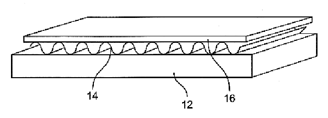
FIG. 1 shows a schematic of a distributed active vibration absorber (DAVA) of the present invention. In the preferred embodiment, the design of the present invention follows a two layer design. The first layer 14 is an active elastic layer with low stiffness per area that can be electrically activated, and is preferably polyvinylidene fluoride (PVDF) having a thickness of 10 .mu.m. The first layer 14 may also be a piezoelectric ceramic, a PZT rubber, an electro mechanical device and the like.

An active elastic layer 14 will be used hereinafter throughout the specification for illustrative purposes. However, it is well understood that any of the above-referenced materials and other materials or multiple layers of materials well known in the art of vibration control may be equally implemented with the present invention. Moreover, for clarity purposes, like numerals will be used for like elements throughout the remaining portions of the specification.

Still referring to FIG. 1, the activ...

second embodiment

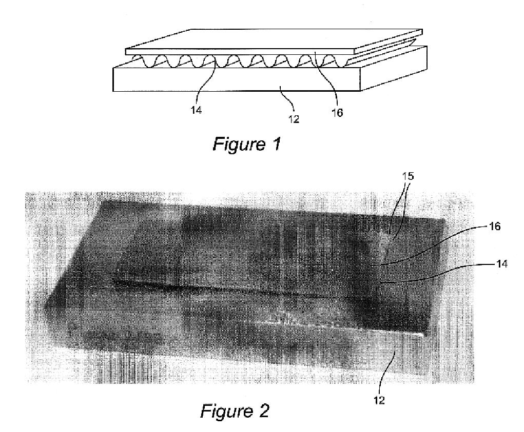
FIG. 6 shows the design of the DAVA of the present invention. In this embodiment, the active elastic layer 14 is corrugated and sandwiched between the beam (e.g., structure 12) and the mass layer 16. The DAVA of this embodiment is 2" wide and is glued onto the beam 12. The mass layer 16 is constant and preferably comprises at least one lead sheet. The DAVA of this embodiment is not thick compared to the beam 12.

Manufacturing Process of the DAVA

FIGS. 7-10 represent the steps of manufacturing the DAVA of the first and second embodiments of the present invention. The main manufacturing fabrication represents the construction of the active elastic layer 14. The first step in manufacturing the active elastic layer 14 is to cut a PVDF sheet (or other similar sheet as discussed above) along its main direction. It is well understood that the PVDF has a direction in which the strains will be greater under active excitation, and this direction is the main vibration direction of the absorber a...


PUM

PropertyMeasurementUnit
Fractionaaaaaaaaaa
Massaaaaaaaaaa
Frequencyaaaaaaaaaa

Abstract

The active/passive absorber for extended vibration and sound radiation control includes principally two layers. The first layer has a low stiffness per unit area which allows motion in the direction perpendicular to its main plane. The second layer is principally a mass layer. These two combined layers have a frequency of resonance close to one of the main structure. The dynamic behavior of the coupled system makes the active/passive absorber a passive absorbe; however, the first layer can be electrically actuated to induce motion in the direction perpendicular to its main plane. This addition property induces and/or changes the motion of the mass layer and therefore improves the dynamic properties of the active/passive absorber system.

Description

1. Field of the InventionThe present invention generally relates to a tunable vibration absorber and, more particularly, to an active / passive tunable distributed vibration absorber for controlling vibration and sound radiation.2. Background DescriptionActive and passive noise reduction control techniques are widely known and commonly used to reduce and / or control vibrations and accompanying sound radiation in vibrating bodies, such as aircraft and the like. In many instances active noise reduction techniques adequately reduce vibrations and noise, but at the cost of expensive and complex control systems. Similarly, passive noise reduction techniques also have been known to reduce vibrations and noise, but these passive systems are typically bulky and heavy and are not effective over low vibration frequencies.Basically, active vibration control systems use a sensor which detects vibration or noise from a vibrating body. The sensor converts the vibration or noise into a signal and the...

Claims


Application Information

Patent Timeline
IPC IPC(8): B32B3/28F16F15/00
CPCB32B3/28F16F15/00Y10S310/80B32B27/304B32B7/12B32B15/08B32B2315/085
Inventor FULLER, CHRISTOPHER R.CAMBOU, PIERRE E.
Owner VIRGINIA TECH INTPROP INC
Why Eureka
Try Eureka