Thin display device

a technology of flat display and rotating mechanism, which is applied in the direction of television systems, electrical apparatus casings/cabinets/drawers, instruments, etc., can solve the problems of large height difference between the left and right edges of the wide display screen unit, and the weight must be supported by the stand, so as to reduce the speed of rotation

Inactive Publication Date: 2006-02-02
SHARP KK
View PDF5 Cites 37 Cited by
  • Summary
  • Abstract
  • Description
  • Claims
  • Application Information

AI Technical Summary

Benefits of technology

[0044] The present invention provides a flat display apparatus comprising a main body unit with a display screen, a stand unit, and a rotation mechanism for rotating the main body unit horizontally with respect to the stand unit, wherein the rotation mechanism is adapted to reduce the speed of rotation u

Problems solved by technology

As the stand-type flat display apparatus becomes larger in size, the display screen correspondingly becomes larger and thus a considerable weight must be supported by the stand.
In the case of a large-sized stand-type flat display apparatus, in par

Method used


Image

  • Thin display device
  • Thin display device
  • Thin display device

Examples


first embodiment

aratus Equipped with Position Adjusting Mechanism

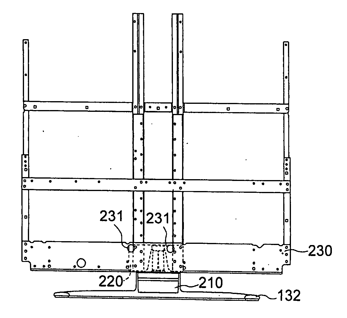
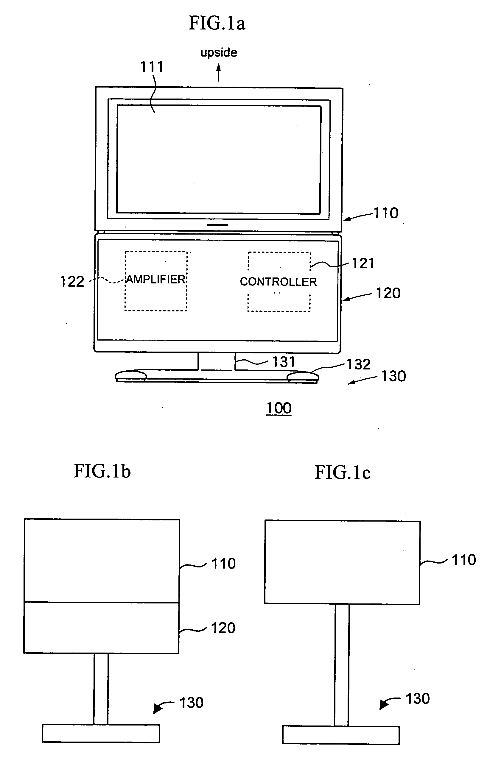
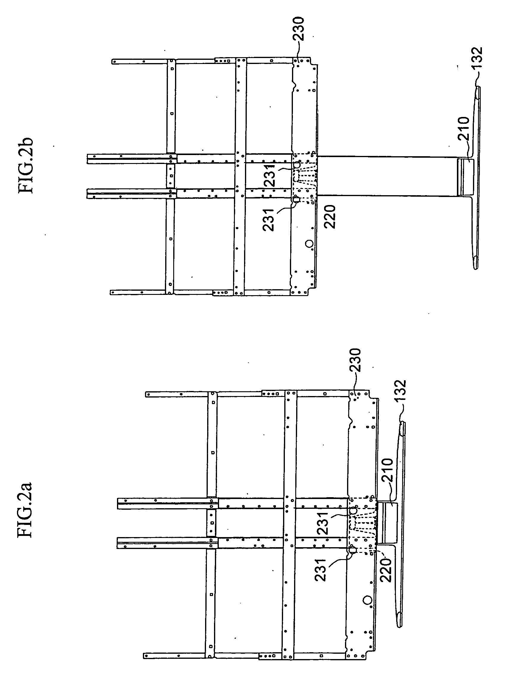
[0075] The position adjusting mechanism of the flat display apparatus according to the present embodiment is used at a stand-supported portion of the stand-type flat display apparatus shown in FIGS. 1 and 2. By the position adjusting mechanism, the rotation unit 210 and the mounting angle 220 securely attached thereto are positioned and secured to the aluminum frame 230.

[0076]FIGS. 3, 4 and 5 are rear, side view and top views, respectively, of the rotation unit 210 and mounting angle 220 of the stand shown in FIG. 2. FIGS. 3(a) and (b) show examples corresponding to FIGS. 1(a) and (b), respectively.

[0077] Referring to FIGS. 3 to 5, the mounting angle 220 includes positioning pins 310, fixing openings 321 to 326, and position adjusting openings 331 to 332. The positioning pins 310 are adapted to engage with bosses 231 (see FIG. 2) extended from a front panel (made of plastic) via the aluminum frame 230, such that the mounting angle 2...

second embodiment

ratus Equipped with a Rotation-Axle Bearing Mechanism

[0090] The rotation-axle bearing mechanism of the flat display apparatus according to the present embodiment is used in the stand-supported portion of the stand-type flat display apparatus shown in FIGS. 1 and 2. The rotation-axle bearing mechanism is built inside the rotation unit 210.

[0091]FIG. 8 shows the rotation unit 210 comprising the rotation mechanism according to the present embodiment. The rotation unit 210 is comprised of an upper unit 810 and a lower unit 820. The upper and lower units are adapted to rotate relative to one another with a predetermined rotation torque. The upper unit 810 is secured to the aluminum frame 230 via the mounting angle 220, and the lower unit 820 is secured to the stand base 132.

[0092]FIG. 9 shows a cross-sectional front elevation of the rotation unit 210. FIG. 10 shows a cross-sectional side elevation of the same unit. FIG. 11 shows a bottom view of the upper unit 810 of the rotation mecha...

third embodiment

aratus Equipped with a Rotation-Speed Reduction Mechanism

[0100] The rotation-speed reduction mechanism of the flat display apparatus according to the present embodiment is used at the stand-supported portion of the stand-type flat display apparatus shown in FIGS. 1 and 2. The rotation-speed reduction mechanism is build inside the rotation unit 210.

[0101]FIG. 13 shows a cross section of the rotation unit 210, in which the rotation mechanism used in the stand-type flat display apparatus of the present embodiment is included. In FIG. 13, the rotation mechanism includes a drive motor 1310, a worm 1311, a first gear 1320, a second gear 1330, a third gear 1340 and a position sensor 1350. The drive motor 1310 is an electric motor. The worm 1311, first gear 1320, second gear 1330 and third gear 1340 are made of plastic, for example.

[0102]FIG. 14 shows a lateral cross section of the rotation mechanism. As will be seen from the figure, the worm 1311 engages with a lower gear of the first ge...


PUM


Abstract

A position adjusting mechanism, a rotation-axle bearing mechanism, and a rotation-speed reduction mechanism for a flat display apparatus. The rotation-speed reduction mechanism comprises a position adjusting mechanism that includes one or more means for securely attaching a stand and a main body unit of the apparatus to one another, and a position adjusting means for adjusting the mounting position of the stand and main body unit. The rotation-axle bearing mechanism comprises a radial bearing and a thrust bearing for supporting a rotation axle between a display screen unit and the stand. The rotation-speed reduction mechanism reduces the speed of rotation between the display screen unit and the stand upon application of a rotation load exceeding a certain level.

Description

TECHNICAL FIELD [0001] The present invention relates to a rotation adjusting mechanism for a stand-type flat display apparatus. In particular, it relates to a position adjusting mechanism for rotating a display screen unit of a stand-type flat display apparatus equipped with a single-axle type rotation mechanism while maintaining the horizontal position of the display screen unit. [0002] The invention further relates to a stand rotation mechanism for a flat display apparatus, particularly to a rotation-axle bearing mechanism for allowing for the rotation of a display unit of a flat display apparatus in a mounting position such that the center of the weight of the main body of the flat display apparatus does not correspond to the central axis of the stand. [0003] The invention further relates to a stand rotation mechanism for a flat display apparatus, particularly to a rotation-speed reduction (or torque limiter) mechanism in the rotation mechanism for reducing the input rotation spe...

Claims


Application Information

Patent Timeline
IPC IPC(8): F16M13/00F16M11/06F16M11/08F16M11/18
CPCF16M11/06F16M11/08Y10S248/919Y10S248/918F16M11/18H04N5/64
Inventor KUGA, TOMIO
Owner SHARP KK
Why Eureka
Try Eureka